Electronic information demagnetizing device

An electronic information and degaussing technology, applied in circuits, magnetic objects, electrical components, etc., can solve problems such as insufficient degaussing and inconvenience for electronic equipment, and achieve the effect of improving service life

Active Publication Date: 2017-10-17
ZHEJIANG JIESHITAI ELECTRONICS
View PDF6 Cites 5 Cited by
  • Summary
  • Abstract
  • Description
  • Claims
  • Application Information

AI Technical Summary

Problems solved by technology

[0007] In order to overcome the disadvantages of insufficient degaussing in the prior art, the inability to degauss in a closed environment and the inconvenient collection of degaussed electronic eq

Method used


Image

  • Electronic information demagnetizing device
  • Electronic information demagnetizing device
  • Electronic information demagnetizing device

Examples


Embodiment 1

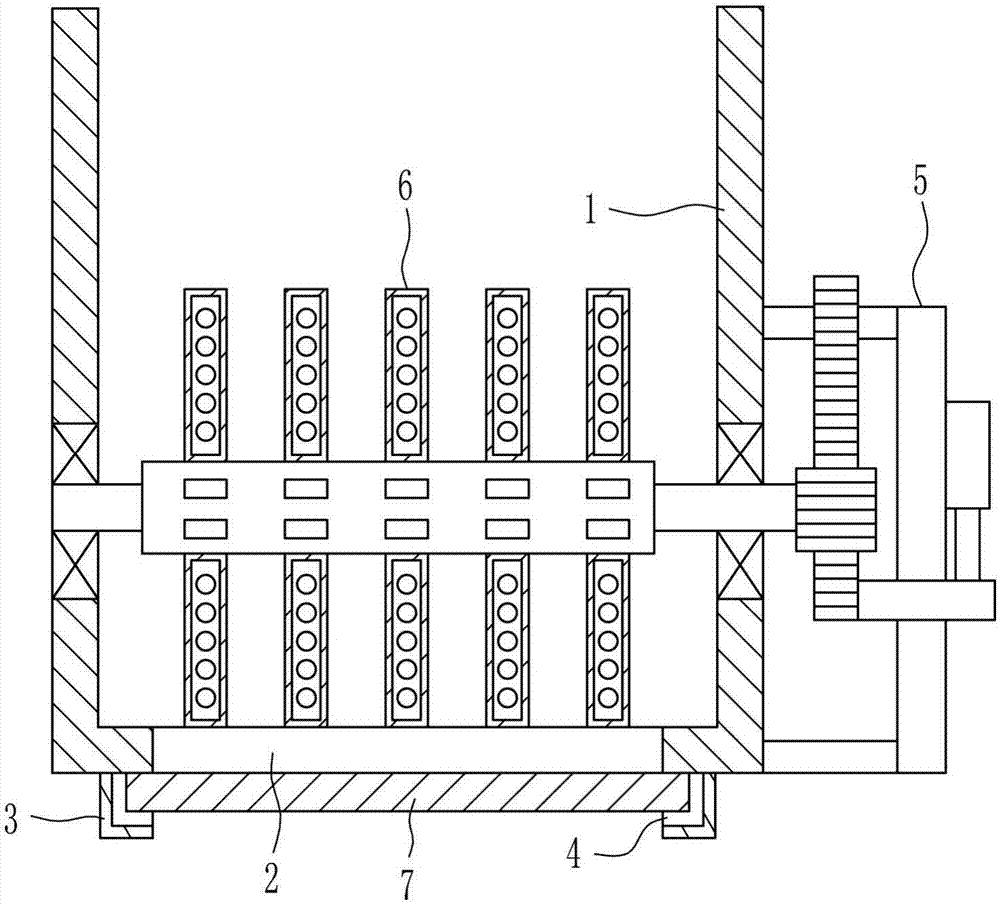
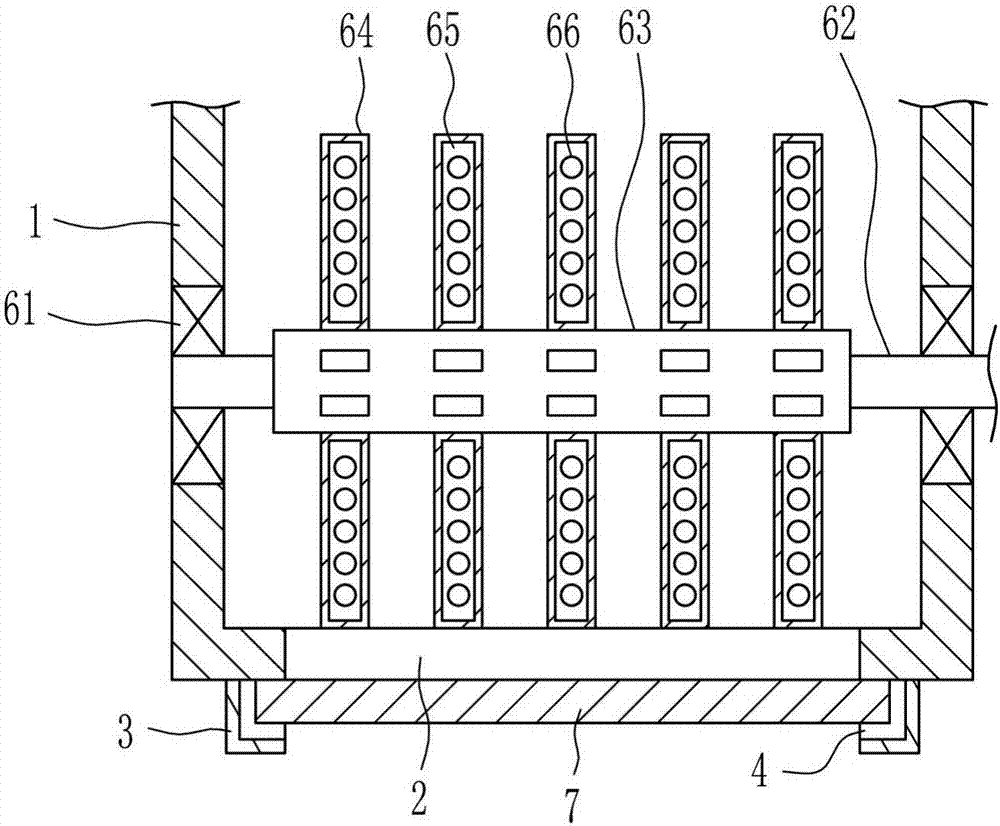
[0035] An electronic information degaussing device, such as Figure 1-5 As shown, it includes a degaussing frame 1, a first fixed block 3, a driving mechanism 5, a degaussing mechanism 6, and a baffle 7. The degaussing mechanism 6 is connected to the inner middle of the degaussing frame 1, and a first through hole is opened in the middle of the inner bottom of the degaussing frame 1. 2. The first through hole 2 is located directly below the degaussing mechanism 6. The left and right sides of the bottom of the degaussing frame 1 are connected to the first fixing block 3. The first fixing block 3 is opened with a first groove 4. Inside the first groove 4 A baffle 7 is provided, the left and right ends of the baffle 7 are located in the first groove 4 , and the drive mechanism 5 is connected to the right side of the degaussing frame 1 .

Embodiment 2

[0037] An electronic information degaussing device, such as Figure 1-5 As shown, it includes a degaussing frame 1, a first fixed block 3, a driving mechanism 5, a degaussing mechanism 6, and a baffle 7. The degaussing mechanism 6 is connected to the inner middle of the degaussing frame 1, and a first through hole is opened in the middle of the inner bottom of the degaussing frame 1. 2. The first through hole 2 is located directly below the degaussing mechanism 6. The left and right sides of the bottom of the degaussing frame 1 are connected to the first fixing block 3. The first fixing block 3 is opened with a first groove 4. Inside the first groove 4 A baffle 7 is provided, the left and right ends of the baffle 7 are located in the first groove 4 , and the drive mechanism 5 is connected to the right side of the degaussing frame 1 .

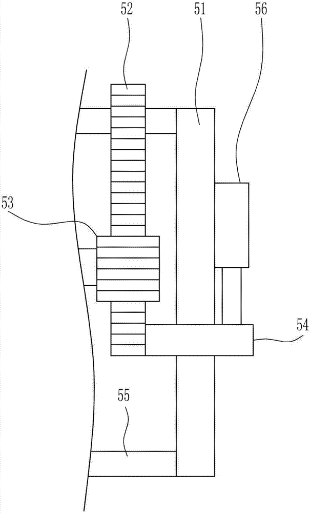
[0038] The driving mechanism 5 includes a slide rail 51, a rack 52, a gear 53, a slide block 54, a connecting rod 55 and an electric push rod 5...

Embodiment 3

[0040] An electronic information degaussing device, such as Figure 1-5 As shown, it includes a degaussing frame 1, a first fixed block 3, a driving mechanism 5, a degaussing mechanism 6, and a baffle 7. The degaussing mechanism 6 is connected to the inner middle of the degaussing frame 1, and a first through hole is opened in the middle of the inner bottom of the degaussing frame 1. 2. The first through hole 2 is located directly below the degaussing mechanism 6. The left and right sides of the bottom of the degaussing frame 1 are connected to the first fixing block 3. The first fixing block 3 is opened with a first groove 4. Inside the first groove 4 A baffle 7 is provided, the left and right ends of the baffle 7 are located in the first groove 4 , and the drive mechanism 5 is connected to the right side of the degaussing frame 1 .

[0041] The driving mechanism 5 includes a slide rail 51, a rack 52, a gear 53, a slide block 54, a connecting rod 55 and an electric push rod 5...


PUM


Abstract

The invention relates to demagnetizing devices, in particular to an electronic information demagnetizing device. The technical problem of the invention is to provide a demagnetizing device which can fully perform demagnetizing, can perform demagnetizing in a sealed environment, and can collect the demagnetized electronic devices. To solve the technical problem, the invention provides the electronic information demagnetizing device. The electronic information demagnetizing device includes a demagnetizing frame; the internal center of the demagnetizing frame is connected to a demagnetizing mechanism; a first through hole is formed in the center of an internal bottom of the demagnetizing frame; the first through hole is positioned under the demagnetizing mechanism; first fixing blocks are connected to a left side and a right side of the bottom of the demagnetizing frame; first grooves are formed in the first fixing blocks; a baffle plate is arranged in the first grooves; a left end and a right end of the baffle plates are positioned in the first grooves; and a right side of the demagnetizing frame is connected to a drive mechanism. The drive mechanism and the demagnetizing mechanism can turn over electronic devices to be demagnetized in the demagnetizing frame.

Description

technical field [0001] The invention relates to a degaussing device, in particular to an electronic information degaussing device. Background technique [0002] Electronic equipment refers to equipment composed of electronic components such as integrated circuits, transistors, and electronic tubes, which use electronic technology and software to play a role, including electronic computers, robots controlled by electronic computers, numerical control or program-controlled systems, etc. [0003] Demagnetization: When the magnetized material is affected by external energy, such as heating and impact, the magnetic moment direction of each magnetic domain will become inconsistent, and the magnetism will weaken or disappear. This process is called demagnetization. [0004] Because the existing process of degaussing electronic equipment cannot fully degauss the electronic equipment that needs to be degaussed, the data may be recovered, and the data will be leaked, which poses a gre...

Claims


Application Information

Patent Timeline
IPC IPC(8): H01F13/00
CPCH01F13/006
Inventor 封雷
Owner ZHEJIANG JIESHITAI ELECTRONICS
Why Eureka
Try Eureka