A UAV-based self-restraint device for traction rope pay-off

A technology of unmanned aerial vehicle and traction rope, applied in the direction of overhead line/cable equipment, etc., can solve the problems of increasing the carrying capacity of the unmanned aerial vehicle, high requirements on the carrying capacity of the unmanned aerial vehicle, and reducing the probability of success, so as to reduce the carrying weight of the pay-off line. , Shorten the payout time, and the effect of low quality

Active Publication Date: 2019-01-04
RES INST OF ECONOMICS & TECH STATE GRID SHANDONG ELECTRIC POWER +1
View PDF6 Cites 0 Cited by
  • Summary
  • Abstract
  • Description
  • Claims
  • Application Information

AI Technical Summary

Problems solved by technology

There are problems with the above-mentioned use of drones to guide the traction line: (1) attaching a sandbag to a section of the traction rope will increase the load capacity of the drone, and the load requirements for the drone will be relatively high; The method will have a certain dependence on the wind direction. If it is against the wind, the probability of successful delivery will be greatly reduced; (3) The traction rope to be delivered is manually placed in the trolley, temporarily anchored, and manual intervention increases the work. cost while reducing work efficiency

Method used


Image

  • A UAV-based self-restraint device for traction rope pay-off
  • A UAV-based self-restraint device for traction rope pay-off
  • A UAV-based self-restraint device for traction rope pay-off

Examples


Embodiment Construction

[0017] Below will combine specific embodiment and appended Figure 1-3 , clearly and completely describe the technical solutions in the embodiments of the present invention, obviously, the described embodiments are only some preferred embodiments of the present invention, not all the embodiments. Those skilled in the art can make similar modifications without departing from the connotation of the present invention, so the present invention is not limited by the specific embodiments disclosed below.

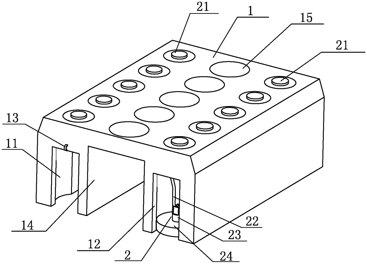
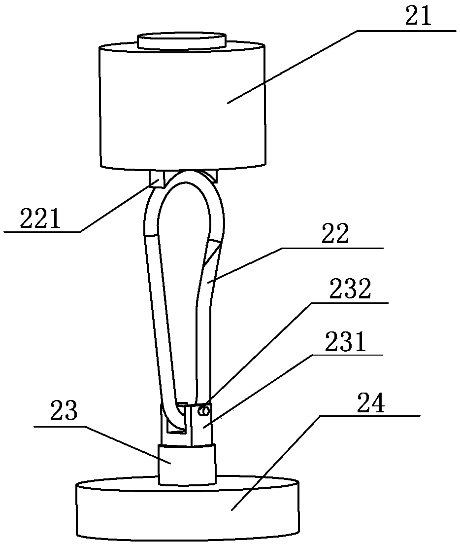
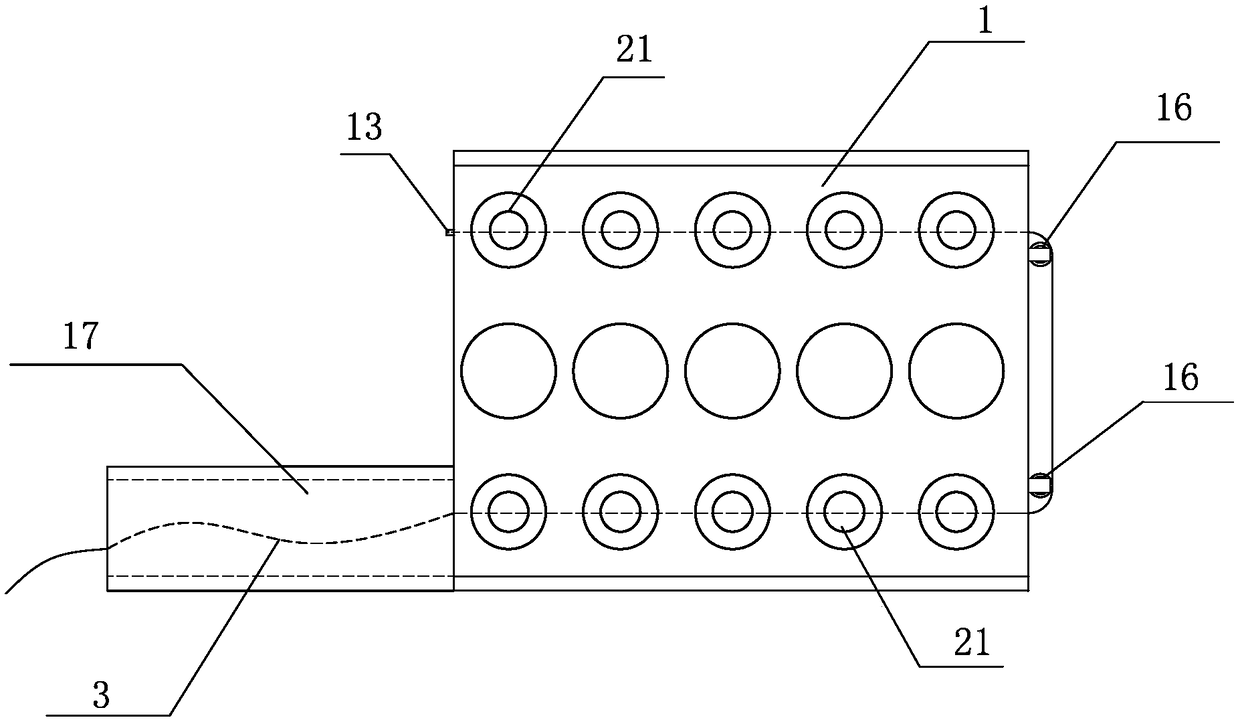
[0018] The present invention provides a self-constraint device based on unmanned aerial vehicle (UAV), including an unmanned aerial vehicle carrier (in order to keep the drawings clear, it is not drawn in the accompanying drawings) and a restraint mechanism, the unmanned aerial vehicle The carrier includes a battery, a control system and a rear camera, the control system is connected to the battery and the rear camera, the rear camera is arranged on the rear side of the drone carr...


PUM


Abstract

The present invention provides a traction rope pay-off self-restraint device based on an unmanned aerial vehicle. The traction rope pay-off self-restraint device comprises an unmanned aerial vehicle carrier and a restraining mechanism, the unmanned aerial vehicle carrier comprises a battery, a control system and a postpositive camera, and the restraining mechanism comprises a fixing pedestal and at least one set of putting mechanisms. Each set of putting mechanisms is arranged in an installing hole on the fixing pedestal, threading grooves penetrating the installing holes transversely are arranged on the fixing pedestal, each set of putting mechanisms comprises a sucker type electromagnet, a buckling ring, a connecting shaft and a circular magnet which are distributed in the installing hole orderly from top to bottom, and a traction rope fixing ring is arranged on the side wall of the front end of the fixing pedestal. The traction rope pay-off self-restraint device can utilize the circular magnets to restrain a traction rope at an appointed pole position automatically without needing the manpower to fix the traction rope temporarily, thereby improving the traction rope pay-off efficiency substantially.

Description

technical field [0001] The invention relates to an unmanned aerial vehicle-based self-restraint device for pulling ropes and releasing wires. Background technique [0002] In the traditional transmission line construction process, the primary traction rope traction is a very challenging and difficult task. Before the drone places the traction line, it is completely completed by manual operation. In some mountainous or river areas, manual traction has Great difficulty and danger. With the use of UAVs in the field of traction line placement, the traction work has become easier, but the slotting and fixing of the traction line still requires manual participation, and has not reached a higher level of automation. The current method for unmanned aerial vehicle to release overhead transmission lines is: attach a sandbag to the end of the traction rope, and use the unmanned helicopter to carry the traction rope to take off. The traction rope carried by the helicopter falls freely...

Claims


Application Information

Patent Timeline
Patent Type & Authority Patents(China)
IPC IPC(8): H02G1/02
CPCH02G1/02
Inventor 苗文静张宏建郑磊刘志强
Owner RES INST OF ECONOMICS & TECH STATE GRID SHANDONG ELECTRIC POWER
Why Eureka
Try Eureka