Resonant converter

A technology of resonant converter and resonant network, applied in the field of resonant converter, can solve the problems of high cost and complex design of two-stage structure, and achieve the effect of improving PF value

Active Publication Date: 2017-10-17
INVENTRONICS HANGZHOU
View PDF6 Cites 2 Cited by
  • Summary
  • Abstract
  • Description
  • Claims
  • Application Information

AI Technical Summary

Problems solved by technology

In the prior art, in order to improve the PF value of the resonant converter, it is often designed as a two-stage structure, the front stage is a PFC circuit, and the rear stage is a resonant conversion circuit. However, the design of the two-stage structure is complicated and the cost is high, so It is necessary to design a resonant converter with a single-stage structure and high PF value

Method used


Image

  • Resonant converter
  • Resonant converter
  • Resonant converter

Examples


Embodiment Construction

[0061] The following will clearly and completely describe the technical solutions in the embodiments of the present invention with reference to the accompanying drawings in the embodiments of the present invention. Obviously, the described embodiments are only some, not all, embodiments of the present invention. Based on the embodiments of the present invention, all other embodiments obtained by persons of ordinary skill in the art without making creative efforts belong to the protection scope of the present invention.

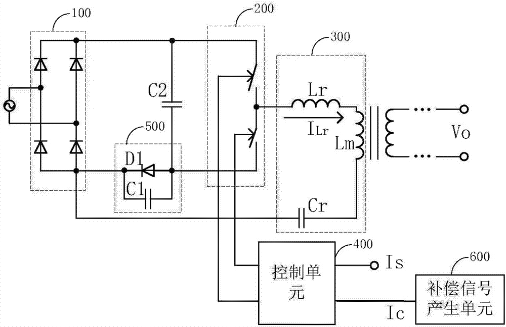
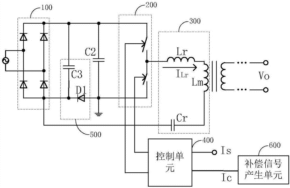
[0062] see figure 1 , the embodiment of the present invention discloses a resonant converter, including a rectifier bridge 100, a bus capacitor C2, a switch unit 200, a resonant network 300, a control unit 400, a shunt unit 500, and a compensation signal generation unit 600, wherein:

[0063] The positive output terminal of the rectifier bridge 100 is connected to one end of the bus capacitor C2;

[0064] The input side of the switch unit 200 is connected in ...


PUM


Abstract

The invention discloses a resonant converter. The resonant converter comprises a rectification bridge, a bus capacitor, a switch unit, a resonance network, a control unit, a shunting unit and a compensation signal generation unit. A positive output terminal of the rectification bridge is connected to one end of the bus capacitor. An input side of the switch unit is connected in parallel to the bus capacitor. An output terminal of the switch unit is connected to a positive input terminal of the resonance network. A negative input terminal of the resonance network is connected to a negative output terminal of the rectification bridge. The shunting unit carries out shunting on a positive resonant current and provides a path for a reversed resonant current. The control unit generates a switch tube driving control signal according to a compensation signal and a sampling signal representing a resonant converter output parameter. A compensation signal indicates the control unit to raise a work frequency of a rectification bridge input voltage zero crossing point position and reduce a work frequency of rectification bridge input voltage peak and valley value positions. The compensation signal generation unit adjusts the compensation signal according to changes of resonant converter output power or a rectification bridge input voltage. In the invention, a PF value of the resonant converter is increased.

Description

technical field [0001] The present invention relates to the technical field of power electronics, and more specifically, relates to a resonant converter. Background technique [0002] Compared with the traditional PWM converter, the resonant converter has smaller switching loss, so it has been widely used. Specifically: the resonant converter uses the resonant circuit as the basic conversion unit. When the circuit resonates, the current or voltage periodically crosses zero, so that the switching device is turned on or off under the condition of zero voltage or zero current, so as to realize soft switching. , to achieve the purpose of reducing switching losses. [0003] The PFC (Power Factor Correction, power factor correction) technology of the resonant converter is a hot research topic in the field of power electronics technology. The lower the PF (Power Factor, power factor) value of the resonant converter will increase the loss of the power grid. In the prior art, in o...

Claims


Application Information

Patent Timeline
Patent Type & Authority Applications(China)
IPC IPC(8): H02M1/42H02M1/12
CPCH02M1/12H02M1/4241Y02B70/10
Inventor 姜德来梅进光
Owner INVENTRONICS HANGZHOU
Why Eureka
Try Eureka