Horizontal type conveying and rotating device for cylindrical workpiece

A rotary device and workpiece technology, applied in conveyors, conveyor objects, mechanical conveyors, etc., can solve the problems of hidden safety hazards, low production efficiency, and high costs, and achieve the effects of high efficiency, reduced production costs, and convenient operation.

Pending Publication Date: 2017-10-20
NANTONG CIMC ENERGY EQUIP CO LTD
View PDF0 Cites 12 Cited by
  • Summary
  • Abstract
  • Description
  • Claims
  • Application Information

AI Technical Summary

Problems solved by technology

However, the cost of hoisting by crane is high, the production efficiency is low, and additional professional hoisting personnel are required, which increases the operating cost of the enterprise, and the hoisting of workpieces between different stations will cause safety hazards to other personnel in the workshop

Method used


Image

  • Horizontal type conveying and rotating device for cylindrical workpiece
  • Horizontal type conveying and rotating device for cylindrical workpiece
  • Horizontal type conveying and rotating device for cylindrical workpiece

Examples


Embodiment Construction

[0035] In order to further illustrate the principle and structure of the present invention, preferred embodiments of the present invention will now be described in detail with reference to the accompanying drawings.

[0036] When describing the orientation in the present invention, the vertical direction is defined as the direction parallel to the conveying direction of the workpiece, the horizontal direction is defined as the direction parallel to the conveying direction of the workpiece, and the up and down directions are defined as the direction perpendicular to the horizontal plane.

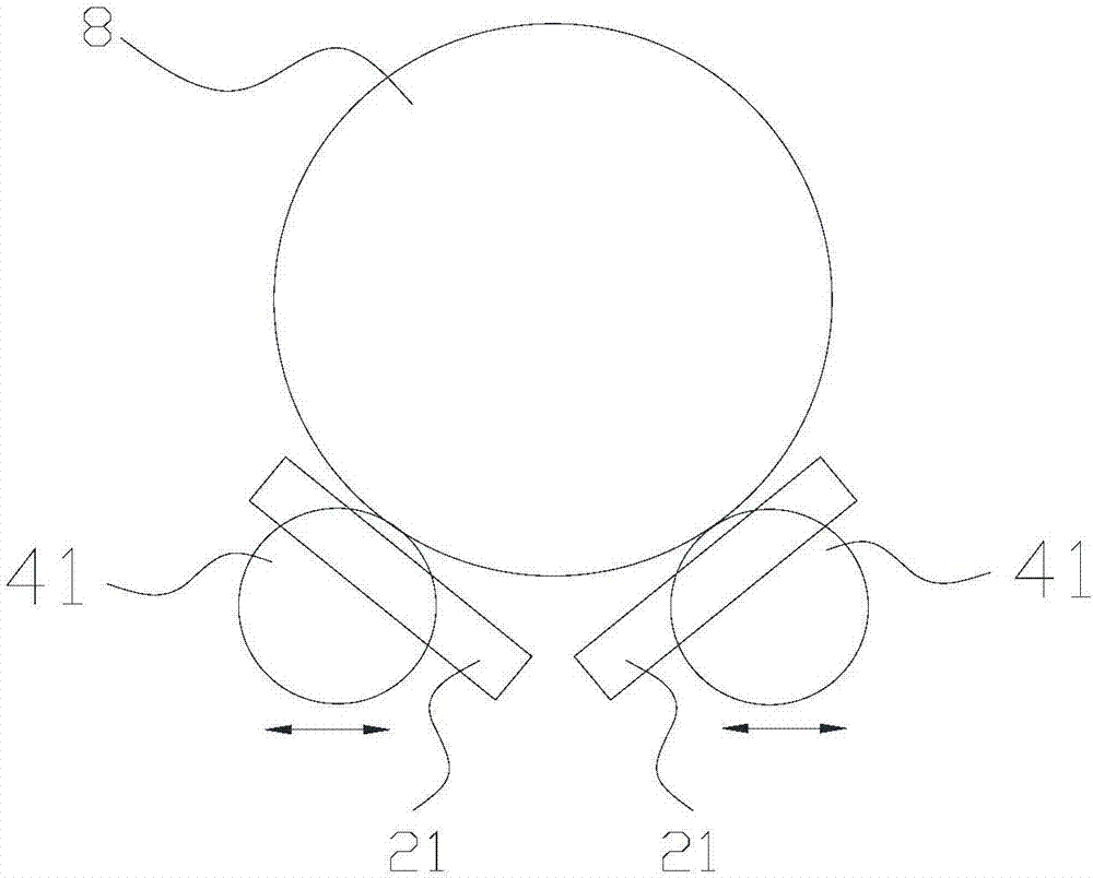
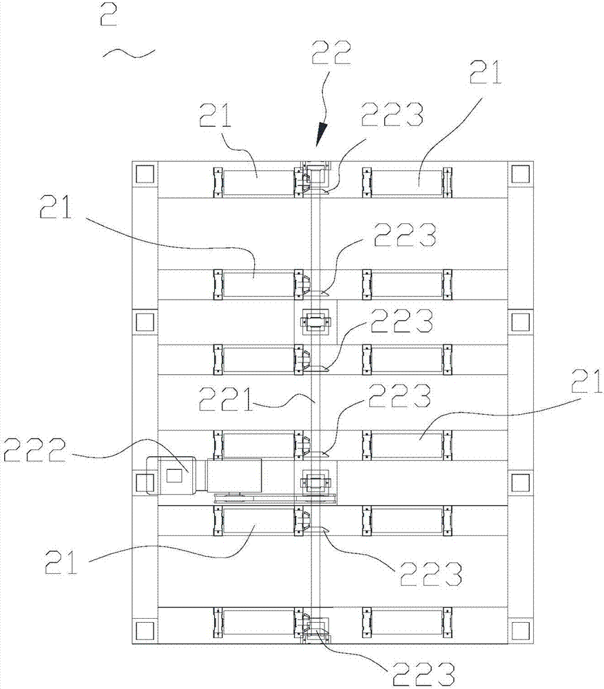
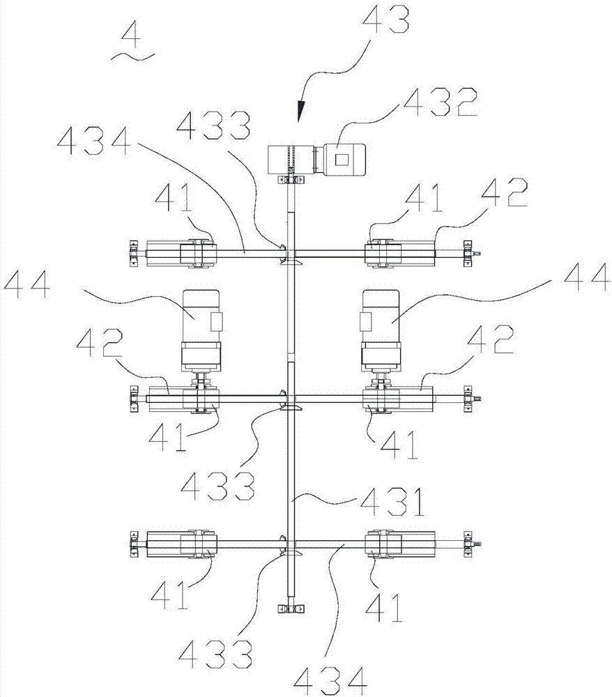
[0037] refer to Figure 1 to Figure 5 , the cylindrical workpiece horizontal conveying and turning device includes: a roller assembly 2 and a roller assembly 4 .

[0038] The roller table assembly 2 includes: a plurality of conveying rollers 21 and a roller table driving mechanism 22, the conveying roller 21 is preferably a rubberized roller, the roller table driving mechanism 22 is connected...


PUM


Abstract

A horizontal type conveying and rotating device for a cylindrical workpiece comprises a roller bed assembly and a rolling wheel assembly. The roller bed assembly comprises multiple conveying rollers and a roller bed drive mechanism, wherein the multiple conveying rollers are used for conveying the cylindrical workpiece arranged on the conveying rollers in the axial direction, and the roller bed drive mechanism is connected with at least one conveying roller and drives the conveying rollers to rotate. The rolling wheel assembly comprises multiple rolling wheels, rolling wheel rotation drive mechanisms and a rolling wheel movement drive mechanism, wherein the multiple rolling wheels are distributed into two groups of rolling wheels, the two groups of rolling wheels are separated from each other, the rolling wheels are arranged between the conveying rollers in a clamped manner, each rolling wheel rotation drive mechanism is connected with at least one rolling wheel and drives the rolling wheels to rotate, and the rolling wheel movement drive mechanism is connected with the two groups of rolling wheels correspondingly and drives the two groups of rolling wheels to move in the direction parallel to the axial direction of the conveying rollers so as to enable the two groups of rolling wheels to be close to each other or far away from each other or drive all the rolling wheels to ascend or descend relative to the conveying rollers to upwards protrude from the top faces of the conveying rollers or be lower than the top faces of the conveying rollers. The horizontal type conveying and rotating device for the cylindrical workpiece is safe, efficient and low in cost.

Description

technical field [0001] The invention relates to a device for realizing multi-process processing of workpieces, in particular to a horizontal workpiece conveying and turning device integrating conveying and turning. Background technique [0002] Due to the large length of some cylindrical workpieces, in order to facilitate production, the method of segmented production is usually adopted, so that each segment of the workpiece is switched to multiple production positions in turn, such as transferring from the longitudinal conveying position to the axial rotation position. The movement mode is changed, and the workpiece needs to be hoisted from the longitudinal conveying tire position by driving. However, hoisting by crane is costly and low in production efficiency, and additional professional hoisting personnel are required, which increases the operating cost of the enterprise, and the hoisting of workpieces between different stations will cause safety hazards to other personn...

Claims


Application Information

Patent Timeline
Patent Type & Authority Applications(China)
IPC IPC(8): B65G37/00B65G13/02B65G13/06B65G39/10B65G35/00
CPCB65G37/00B65G13/02B65G13/06B65G35/00B65G39/10
Inventor 卫晓峰张德林崔洪鹏殷志炎李玉清
Owner NANTONG CIMC ENERGY EQUIP CO LTD
Why Eureka
Try Eureka