Drag-reduction guiding unloading device and pushing method for pushing and constructing combined bridge

An unloading device and jacking technology, which is used in bridges, bridge construction, erection/assembly of bridges, etc., can solve the problems of difficult to remove friction reducing gaskets, large sliding friction, and difficult lateral offset constraints, so as to reduce personnel and The effect of auxiliary equipment configuration, reducing construction cost and convenient dismantling

Active Publication Date: 2017-10-20
CHONGQING JIAOTONG UNIVERSITY
View PDF7 Cites 9 Cited by
  • Summary
  • Abstract
  • Description
  • Claims
  • Application Information

AI Technical Summary

Problems solved by technology

[0003] The "Segmental Continuous Prefabrication—Steel-Concrete Composite Beam Bridge and Its Construction Method" (Invention Patent Application No.: 201611148449.8) filed by the inventor in the previous period is much better than the construction of conventional fabricated steel-concrete composite girder bridges. It avoids the trouble of large-scale transportation, hoisting and cast-in-place combined concrete construction, but there is a problem of segmental continuous precast concrete bridge slabs being pushed into place on steel beams for a long distance. The usual method is to contact the concrete bridge slabs with steel beams The interface is equipped with gaskets to reduce sliding friction, but in the case of long-distance pushing into place, there must be excessive sliding friction, and it is difficult to restrain the lateral offset, and it is not easy to remove the concrete bridge slab after it is in place on the top surface of the steel beam to reduce friction Three major problems of the resistance gasket

Method used


Image

  • Drag-reduction guiding unloading device and pushing method for pushing and constructing combined bridge
  • Drag-reduction guiding unloading device and pushing method for pushing and constructing combined bridge
  • Drag-reduction guiding unloading device and pushing method for pushing and constructing combined bridge

Examples


Embodiment Construction

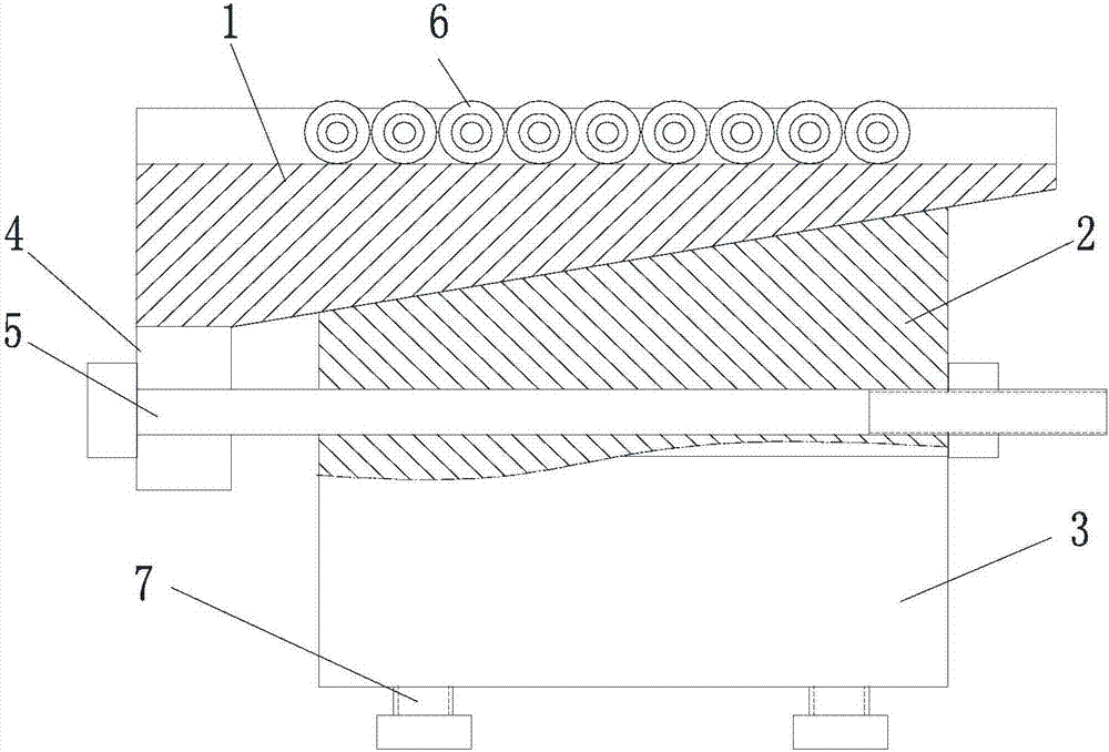
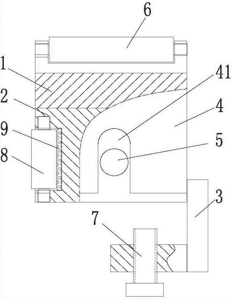
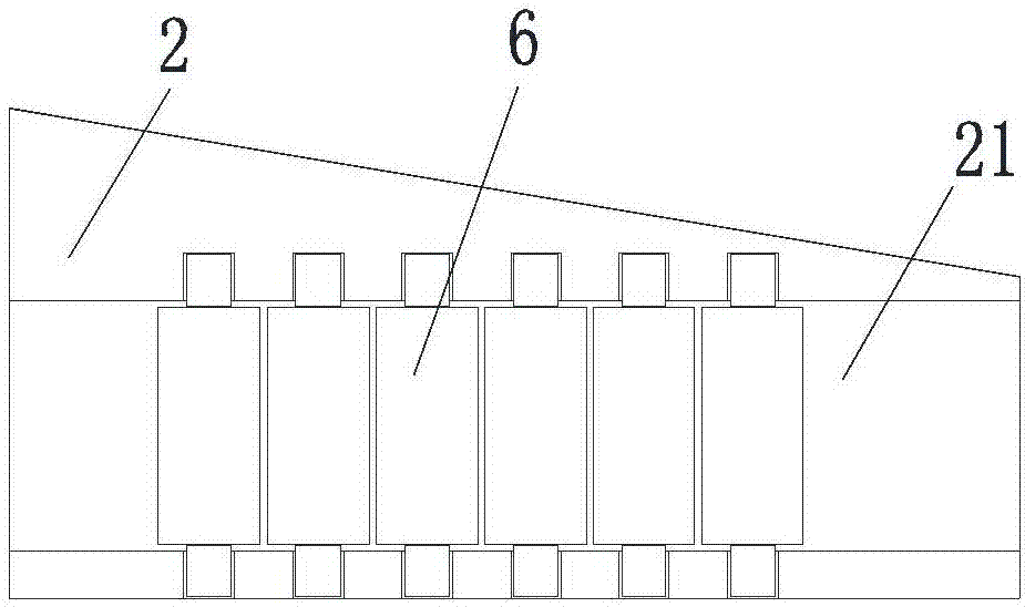
[0028] figure 1 is a schematic diagram of the longitudinal partial cross-sectional structure of the guide device, figure 2 It is a schematic diagram of the lateral partial cross-sectional structure of the guide device, image 3 Schematic diagram of the structure of the lower wedge, Figure 4 A longitudinal schematic diagram of the application structure for the guide, Figure 5 It is a horizontal schematic diagram of the application structure of the guide device. The drag reduction guide unloading device for pushing and constructing a composite bridge in this embodiment includes a lower support assembly and an upper sliding support, and the upper sliding support is arranged in a height-adjustable manner. The lower support assembly, the lower support assembly is fixed to the steel beam 13 of the bridge when in use, and the side of the drag reduction guide unloading device opposite to the side elevation of the rib 11 of the concrete bridge slab is provided with a guide surface...


PUM


Abstract

The invention discloses a drag-reduction guiding unloading device and pushing method for pushing and constructing a combined bridge. An upper sliding support piece with an adjustable height is arranged on a lower support assembly, and the lower support assembly is fixed to a steel girder in use; the face, opposite to the side face of a rib of a concrete bridge-road plate, of the drag-reduction guiding unloading device is provided with a guiding face for providing guidance in a rolling fraction mode when the concrete bridge-road plate is pushed, and the upper sliding support piece is used for supporting wing plates of the concrete bridge-road plate in a rolling fraction mode when in use. Through the adoption of the drag-reduction guiding unloading device and pushing method for pushing and constructing the combined bridgen, the contact and sliding fraction between the bridge-road plate and the steel girder is converted into rolling fraction, and the forward resistance to pushing of the concrete bridge-road plate is obviously reduced; the transverse position of the slab rib of the concrete bridge-road plate is restrained by the lower support assembly through the guiding face, so that it is guaranteed that transverse guidance is provided for push forwarding of the concrete bridge-road plate on the steel girder along a set trajectory; by adjusting the height of the upper sliding support piece, the gravity, supported by the device, of the concrete bridge-road plate can be conveniently unloaded and transferred to the top face of the steel girder.

Description

technical field [0001] The invention belongs to the field of bridge engineering equipment, and in particular relates to a drag-reducing guiding unloading device and a pushing method for building a steel-concrete composite bridge by pushing. Background technique [0002] The common construction method of the existing prefabricated steel-concrete composite girder bridge is hoisting the steel girder to put it in place on the pier, hoisting the prefabricated concrete bridge slab to put it in place on the steel girder, and re-casting combined concrete to form a steel-concrete composite girder bridge. [0003] The "Segmental Continuous Prefabrication—Steel-Concrete Composite Beam Bridge and Its Construction Method" (Invention Patent Application No.: 201611148449.8) filed by the inventor in the previous period is much better than the construction of conventional fabricated steel-concrete composite girder bridges. It avoids the trouble of large-scale transportation, hoisting and cas...

Claims


Application Information

Patent Timeline
Patent Type & Authority Applications(China)
IPC IPC(8): E01D21/00
CPCE01D21/00
Inventor 周志祥曾兴祁乔心格郑佳燕
Owner CHONGQING JIAOTONG UNIVERSITY
Why Eureka
Try Eureka