High bearing capacity steel pipe joint and manufacturing method

A production method and bearing capacity technology, applied in the direction of instruments, electrical digital data processing, computer-aided design, etc., can solve the problems of ring plate welding production difficulties, material waste, and welding processing difficulties, so as to improve economic and social benefits, The effect of saving material consumption and reducing force transmission distance

Active Publication Date: 2017-10-20
ZHEJIANG ELECTRIC POWER DESIGN INST +1
View PDF6 Cites 4 Cited by
  • Summary
  • Abstract
  • Description
  • Claims
  • Application Information

AI Technical Summary

Problems solved by technology

[0004] 1) When the single ring plate stiffening joint is applied to complex joints, the force transmission distance between the branch pipe and the ring plate is too long, which may easily cause the instability of the joint plate, and although the thickened joint plate can prevent instability, it will cause material waste , Welding processing difficulties and other issues;
[0005] 2) The single-ring ring-plate joint needs to be supplemented by structural ring plates to prevent the instability of the joint plate, but it cannot play the bearing role of the structural ring plate, resulting in unnecessary waste;
[0006] 3) Main bearing capacity When the bearing capacity of the ring plate is not enough, it is necessary to increase the bearing capacity by increasing the height and thickness of the ring plate, and the increase in height will easily lead to the out-of-plane instability of the ring plate, and the ring plate that is too thick will cause the ring plate to bring Difficulties in welding production

Method used


Image

  • High bearing capacity steel pipe joint and manufacturing method
  • High bearing capacity steel pipe joint and manufacturing method

Examples


Embodiment Construction

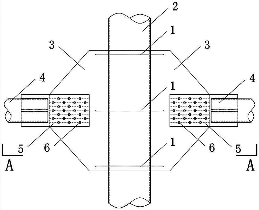
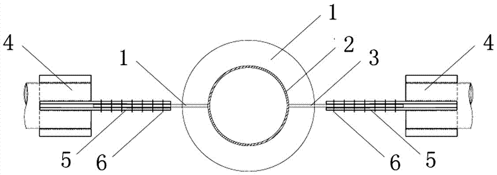
[0032] The present invention will be further described below in conjunction with accompanying drawing and specific embodiment: figure 1 , 2 As shown, a high-capacity steel pipe tower node described in the present invention is used to connect the main pipe 2 and a plurality of branch pipes 4 of the steel pipe tower. The gusset plate 3 of the component for transmitting force and preventing the instability of the ring plate is arranged in the area of ​​the gusset plate 3 with a plurality of load-bearing circular ring plates 1 as the main force-bearing components, and each circular ring plate 1 is connected with the main pipe 2 and The gusset plate 3 is vertical and welded.

[0033] As shown in the figure, the branch pipe 4 and the gusset plate 3 are connected by welding, U-shaped plate 5 or cross plate; the gusset plate 3 is kept as a continuous plate, while the circular ring plate 1 is The gusset plate 3 is fixed on the gusset plate 3 by cutting first and then welding. The pos...


PUM


Abstract

The invention provides a high bearing capacity steel pipe tower joint and a manufacturing method. The high bearing capacity steel pipe joint is used for connecting a main pipe and a plurality of branch pipes of a steel pipe tower. A joint plate serving as a component of force transmission and preventing instability out of a ring plate face is welded to the plane formed by the branch pipes and the main pipe in the generatrix direction of the main pipe, a plurality of bearing round ring plates serving as main bearing components are arranged in a joint plate area, and each round ring plate is perpendicular to and welded to the main pipe and the joint plate. The manufacturing method includes the steps that when manufacturing a joint used for connecting a plurality of steel pipes, firstly a main bearing component with the relative long pipe diameter needs to be determined as a main pipe, and other to-be-connected steel pipes serve as branch pipes; a plane formed by the main pipe and the multiple branch pipes is considered, in the plane, the joint plate is welded in the generatrix direction of the outer wall of the main pipe, the size of the joint plate need to be large enough to contain each branch pipe which needs to be connected, and the branch pipes are not overlapped mutually; the meeting point of the axle of the branch pipes and the main pipe needs to be in the range of the joint plate; and by adopting the manufacturing method, the bearing capacity of the steel pipe tower joint is improved greatly.

Description

technical field [0001] The present invention relates to a steel pipe node with high bearing capacity and its manufacturing method, and more specifically relates to a steel pipe node and related calculation method when the steel pipe main pipe and the branch pipe of the steel pipe iron tower of the overhead transmission line are connected and the related calculation method belongs to the high bearing capacity Force steel pipe joints and calculation technology. Background technique [0002] With the continuous improvement of the transmission capacity and voltage level of transmission lines, the height and load of transmission towers, steel pipe towers have been used more and more. Correspondingly, greater loads have higher and higher requirements on the bearing capacity of nodes. The joints in the steel pipe tower are an important part of the steel pipe tower structure. The damage of the joints will lead to the collapse of the entire structure. Therefore, a safe, reliable, ec...

Claims


Application Information

Patent Timeline
Patent Type & Authority Applications(China)
IPC IPC(8): E04B1/58E04B1/24E04H12/08G06F17/50B23P15/00
CPCE04B1/2403E04H12/08B23P15/00E04B2001/2406G06F30/17G06F2119/06Y02E10/72
Inventor 郭勇邢月龙陈勇李捍平沈建国王宁潘峰陈成
Owner ZHEJIANG ELECTRIC POWER DESIGN INST
Why Eureka
Try Eureka