Automobile exhaust catalyst

A technology of automobile exhaust and catalytic converter, which is applied in the direction of exhaust gas treatment, exhaust device, machine/engine, etc., which can solve the problem that the catalytic converter of exhaust gas is not very ideal, the efficiency and effect of exhaust gas treatment are poor, and the working status of the catalytic converter cannot be reflected in real time and other problems, to achieve the effect of reasonable and novel structure design, good catalytic effect and improved catalytic efficiency

Inactive Publication Date: 2017-10-20
WUHU EVERSHINE AUTOMOTIVE COMPONENT
View PDF6 Cites 3 Cited by
  • Summary
  • Abstract
  • Description
  • Claims
  • Application Information

AI Technical Summary

Problems solved by technology

[0002] Catalyst refers to a catalytic device that converts harmful gases such as CO, HC and NOx emitted from automobile exhaust into harmless carbon dioxide, water and nitrogen through oxidation and reduction. The exhaust gas treatment efficiency and effect of existing catalytic converters are poor. And it cannot reflect the working status of the catalytic converter in real time
[0003] In addition, the catalysis of the existing exhaust gas catalytic converter is not very ideal

Method used


Image

  • Automobile exhaust catalyst
  • Automobile exhaust catalyst

Examples


Embodiment 1

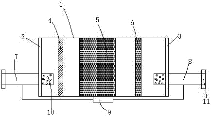
[0028] see figure 1 and figure 2 , the present invention provides an automobile exhaust catalyst, comprising: a housing 1, a front end cover 2 and a rear end cover 3 respectively arranged at the front end and the rear end of the housing 1, arranged at intervals from the front end to the rear end of the housing The turbulence plate 4, the catalyst core 5 and the particle filter 6, and the inlet pipe 7 and the outlet pipe 8 respectively inserted into the front end and the rear end of the housing 1, and the outer surface of the housing 1 A differential pressure sensor 9 is connected with the inlet pipe 7 and the outlet pipe 8;

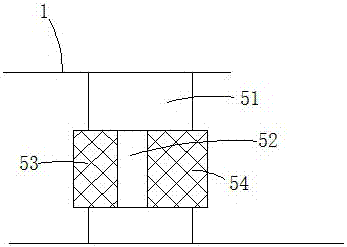
[0029] The catalyst core 5 includes: a fixing plate 51 fixed in the housing 1, a mounting hole 52 provided in the fixing plate 51, and first catalytic converters arranged at intervals along the axial direction of the mounting hole 52. The core 53 and the second catalytic core 54 , and the catalyst coating provided on the first catalytic core 53 and the...

Embodiment 2

[0034] A kind of manufacturing process of the catalytic converter core of automobile exhaust catalytic converter, the steps are as follows:

[0035] ①, structure and molding

[0036] The catalyst core includes a fixing plate fixed in the casing, a mounting hole arranged in the fixing plate, a first catalytic core and a second catalytic core arranged at intervals along the axial direction of the mounting hole, and Catalyst coating on the second catalytic core;

[0037] The material of the fixed plate is Q235 steel, and the mounting hole is formed by stamping;

[0038] The first catalytic core and the second catalytic core are prepared according to the prior art, and the catalyst coating is prepared and loaded according to the prior art;

[0039] ②, catalytic core pretreatment

[0040] Soak the first catalytic core and the second catalytic core in the pretreatment solution for at least 15 minutes, then take them out and dry them directly;

[0041] The pretreatment liquid is ...


PUM


Abstract

The invention relates to the technical field of automobile exhaust treatment, in particular to an automobile exhaust catalyst. The automobile exhaust catalyst comprises a shell, a front end cover, a rear end cover, a turbulence plate, a catalyst core, a particulate matter filter, an air inlet pipe, an air outlet pipe and a differential pressure transducer, wherein the front end cover and the rear end cover are arranged at the front end and the rear end of the shell respectively, the turbulence plate, the catalyst core and the particulate matter filter are arranged at intervals in sequence from the front end of the shell to the rear end of the shell, the air inlet pipe and the air outlet pipe are inserted into the front end and the rear end of the shell respectively, and the differential pressure transducer is arranged on the outer surface of the shell and connected with the air inlet pipe and the air outlet pipe; the catalyst core comprises a fixed plate fixed into the shell, a mounting hole formed in the fixed plate, a first catalyst core body, a second catalyst body and catalyst coatings, wherein the first catalyst core body and the second catalyst core body are arranged in a spaced mode in the axial direction of the mounting hole, and the catalyst coatings are arranged on the first catalyst core body and the second catalyst core body; the exhaust treatment efficiency and the exhaust treatment effect of the catalyst can be improved, and the working state of the catalyst can be reflected in real time.

Description

technical field [0001] The invention relates to the technical field of automobile exhaust gas treatment, in particular to an automobile exhaust gas catalytic converter. Background technique [0002] Catalyst refers to a catalytic device that converts harmful gases such as CO, HC and NOx emitted from automobile exhaust into harmless carbon dioxide, water and nitrogen through oxidation and reduction. The exhaust gas treatment efficiency and effect of existing catalytic converters are poor. And it cannot reflect the working state of the catalytic converter in real time. [0003] In addition, the catalysis of the existing exhaust gas catalytic converter is not very ideal. Contents of the invention [0004] The technical problem to be solved by the present invention is to provide an automobile exhaust gas catalytic converter, which can improve the exhaust gas treatment efficiency and exhaust gas treatment effect of the catalytic converter, and can reflect the working state of ...

Claims


Application Information

Patent Timeline
Patent Type & Authority Applications(China)
IPC IPC(8): F01N3/035F01N3/28F01N11/00
CPCF01N3/035F01N3/2803F01N3/2892F01N11/002Y02A50/20Y02T10/40
Inventor 刘华
Owner WUHU EVERSHINE AUTOMOTIVE COMPONENT
Why Eureka
Try Eureka