Zero-thrust multifunctional rotating compensator and manufacturing method thereof

A rotary compensator, multi-functional technology, applied in the expansion compensation device, adjustable connection, passing element and other directions of pipelines, can solve the problems of increasing rotation resistance, pipeline thermal loss, affecting economic benefits, etc., to achieve enhanced sealing effect , prolong the service life, save energy and protect the environment

Pending Publication Date: 2017-10-20
JIANGSU YONGLI PIPELINE CO LTD
View PDF7 Cites 1 Cited by
  • Summary
  • Abstract
  • Description
  • Claims
  • Application Information

AI Technical Summary

Problems solved by technology

[0003] Existing rotary compensators generally have the following problems in high-temperature and high-pressure environments: the fit gap between the rotating parts is large, and the relative rotation stability of the inner and outer pipes is poor due to the thrust of the pipeline, which is prone to eccentric deflection of different axes and increases the rotation resistance , reducing the flexibility of rotation compensation
In the prior art, steel balls are usually used as the rolling friction pair to control the coaxial rotation of the inner and outer tubes. The structure is complex and the processing is difficult.
The bearing load of the steel ball is small, and it is easy to wear or be crushed when used in high-pressure pipelines. After a period of use, it will affect the sealing performance of the sealing packing, resulting in sealing failure and leakage.
resulting in heat loss in the pipeline
If it is not found and maintained in time, it may even cause safety production accidents, which will not only directly affect economic benefits, but also cause environmental problems.

Method used


Image

  • Zero-thrust multifunctional rotating compensator and manufacturing method thereof

Examples


Embodiment Construction

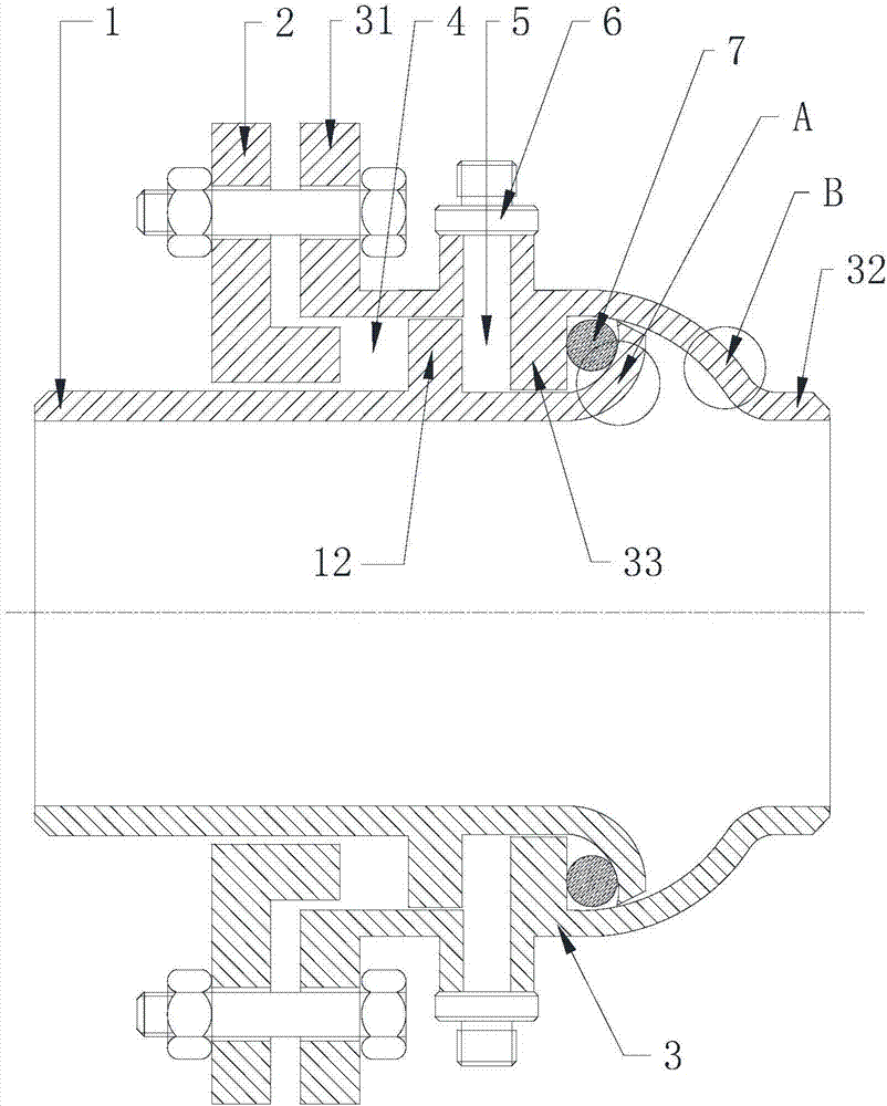
[0026] Below in conjunction with accompanying drawing and specific embodiment the present invention will be further described:

[0027] Such as figure 1 As shown, the non-thrust multifunctional rotary compensator includes a rotary tube 1 and a rotary seat 3, one end of the rotary seat 3 is provided with a rotary seat flange 31, and the rotary tube 1 is sleeved in the rotary seat 3, and the rotary seat 3 The other end is provided with an arc-shaped contraction tube B, the side of the rotary seat flange 31 is provided with a packing gland flange 2, the outer circumference of the rotary tube 1 is provided with a rotary tube convex ring 12, and the inner wall of the rotary seat 3 is provided with a packing ring 33 , the stuffing gland flange 2, the rotating pipe convex ring 12 and the rotating seat 3 constitute the first packing chamber 4, the rotating pipe convex ring 12 and the packing ring 33 of the rotating seat 3 constitute the second packing chamber 5, and the rotating pipe ...


PUM


Abstract

The invention relates to a zero-thrust multifunctional rotating compensator and a manufacturing method thereof. The compensator comprises a rotating pipe and a rotating seat; one end of the rotating seat is provided with a rotating seat flange, and the other end of the rotating seat is provided with an arc-shaped shrinkage pipe; one side of the rotating seat flange is provided with a gland flange; the outer circumference of the rotating pipe is provided with a convex ring; the inner wall of the rotating seat is provided with a packing ring; the gland flange and the convex ring of the rotating pipe form a first packing cabin; the convex ring of the rotating pipe and the packing ring of the rotating seat form a second packing cabin; the end, close to the arc-shaped shrinkage pipe of the rotating seat, of the rotating pipe is provided with a port which is outwards turned; and an end surface sealing ring is arranged between the outwards-turned port of the rotating pipe and the packing ring of the rotating seat. The manufacturing method comprises the steps: (1) outwards turning the end of the rotating pipe; (2) arranging a metal end surface sealing ring; and (3) stretching the end of the rotating seat to form an arc-shaped pipe which is inwards shrunk. The zero-thrust multifunctional rotating compensator is suitable for a high-pressure heat pipe network, free of welding in whole, high in bearing strength, free of eccentricity, good in sealing performance, safe and reliable in use and long in product life.

Description

technical field [0001] The invention relates to the technical field of pipeline compensators, in particular to a non-thrust multifunctional rotary compensator and a manufacturing method of the rotary compensator. Background technique [0002] At present, when the existing heat pipe network transports hot water, steam and other high-temperature media, due to the thermal expansion and contraction of the pipeline due to the influence of the medium temperature, the telescopic compensator or rotary compensator is generally used to compensate the displacement of the pipeline. Because the displacement of the compensation pipe is compensated by the expansion and contraction of the sliding core tube, the compensation ability of the sleeve expansion joint is limited by the structure, and the seal between the sliding core tube and the packing cannot be kept in good condition for a long time, and it is prone to leakage after long-term use. The structure of the rotary compensator usually...

Claims


Application Information

Patent Timeline
Patent Type & Authority Applications(China)
IPC IPC(8): F16L51/00F16L27/08
CPCF16L27/0804F16L51/00
Inventor 潘文浩潘海山徐彩仙
Owner JIANGSU YONGLI PIPELINE CO LTD
Why Eureka
Try Eureka