Multi-stream reducer tube wound heat exchanger

A coiled tube heat exchanger, multi-flow technology, applied in the direction of indirect heat exchangers, heat exchanger types, fixed tubular conduit components, etc., can solve the need for improvement in the coiled tube structure and layout, shell side fluid flow resistance Large, shell-side fluid turbulence effect and reduced convective heat transfer effect, etc., to improve the comprehensive heat transfer effect, reduce the total weight, enhance turbulence and convective heat transfer effect

Active Publication Date: 2019-08-30
LUOYANG LONGHUI PETROCHEM ENG
View PDF6 Cites 0 Cited by
  • Summary
  • Abstract
  • Description
  • Claims
  • Application Information

AI Technical Summary

Problems solved by technology

[0003] There are two types of existing coiled heat exchangers: single flow and multiple streams, but no matter which type, the heat exchange tubes of the same diameter are used in the coiled heat exchangers, and the coiled tubes are placed in the core tube. The outer tightly wound, both the axial distance and the transverse distance are very small, resulting in a large flow resistance of the shell-side fluid, and a decrease in the disturbance effect and convective heat transfer effect of the shell-side fluid
Therefore, the structure and arrangement of the coiled tubes in the coiled tube heat exchanger need to be improved.

Method used


Image

  • Multi-stream reducer tube wound heat exchanger
  • Multi-stream reducer tube wound heat exchanger

Examples


Embodiment Construction

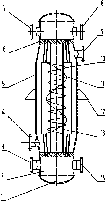
[0014] The assembly process of the multi-flow reducer tube-wound heat exchanger will be further described below with reference to the accompanying drawings.

[0015] Taking the double-tube-sheet double-flow reducer tube-wound heat exchanger as an example, first, the core tube and the tube sheets at both ends are welded and fixed, and then each layer of winding tubes is made of winding tubes of various diameters according to the The designed helix angles are wound outside the core barrel in turn, and then, the two ends of all the wound pipes are divided into two tube bundles according to the diameter of the tubes, and the two tube bundles at one end penetrate into the two areas of the same tube sheet respectively, and the two tube bundles at the other end The two tube bundles respectively penetrate into the two areas corresponding to another tube sheet.

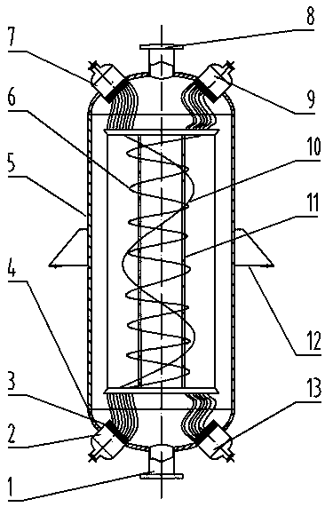
[0016] For the four-tube-sheet double-flow reducer tube-wound heat exchanger, firstly, the core tube and the circular frame ...


PUM


Abstract

The invention discloses a multi-flow reducing pipe winding pipe type heat exchanger which comprises a shell, a pipe box, pipe plates, a core barrel, winding pipes, locating strips, a shell pass inlet pipe, a shell pass outlet pipe, pipe pass inlet pipes, pipe pass outlet pipes, pass partition plates and a lug type support. The multi-flow reducing pipe winding pipe type heat exchanger is characterized in that each winding pipe layer outside the core barrel is formed by alternately winding the winding pipes of at least two pipe diameters, and the axial distance between the winding pipes on the same layer is located through the corresponding locating strip; the winding pipes on the adjacent inner layer and outer layer are the same in spiral angle and opposite in winding direction; the two ends of each of all the winding pipes are each divided into two pipe bundles according to the pipe diameters, and the two pipe bundles of each end are arranged in two areas of the same pipe plate correspondingly; and the corresponding pass partition plate is arranged on each pipe plate and in the pipe box so as to divide the two corresponding areas, and the two pipe bundles of each end can be arranged on two small pipe plates correspondingly. According to the multi-flow reducing pipe winding pipe type heat exchanger, multiple strands of flow of a pipe pass can be subjected to heat exchange with flow of a shell pass at the same time, through the alternate arrangement of the reducing winding pipes, the radial clearances between the winding pipes are increased, and the comprehensive heat exchange effect of the flow of the shell pass is enhanced.

Description

technical field [0001] The invention relates to the technical field of shell-and-tube heat exchangers, in particular to a coil-wound heat exchanger with multi-flow different-diameter tubes. Background technique [0002] Heat exchangers play an important role in energy, power, chemical, petroleum and many other industrial productions. The tube-wound heat exchanger is a shell-and-tube heat exchanger with compact structure and high heat exchange efficiency. It mainly includes main parts such as tube box, tube sheet, shell, core tube and coil tube. The central position of the tube sheets at both ends is used as the support for the winding tube bundle, and the multi-layer winding tubes are wound outside the core tube. [0003] There are two types of existing coiled heat exchangers: single flow and multiple streams, but no matter which type, the heat exchange tubes of the same diameter are used in the coiled heat exchangers, and the coiled tubes are placed in the core tube. The ...

Claims


Application Information

Patent Timeline
Patent Type & Authority Patents(China)
IPC IPC(8): F28D7/00F28F1/00
Inventor 吴金星王蕾田倩卉
Owner LUOYANG LONGHUI PETROCHEM ENG
Why Eureka
Try Eureka