Miniature printing logarithmic cycle antenna based on unit bending

A logarithmic period antenna and bending technology, applied in the direction of antenna grounding switch structure connection, radiation element structure, etc., can solve the problems of large structural size, limited use of several period antennas, large size of several period antennas, etc., to reduce the overall effect of size

Inactive Publication Date: 2017-10-20
NANJING UNIV OF POSTS & TELECOMM
View PDF2 Cites 8 Cited by
  • Summary
  • Abstract
  • Description
  • Claims
  • Application Information

AI Technical Summary

Problems solved by technology

[0003] Since log-periodic antennas are often used for indoor distribution and elevator signal coverage, the use of log-periodic antennas is severely limited due to their large structural size, and there is a problem of large size of traditional printed log-periodic antennas

Method used


Image

  • Miniature printing logarithmic cycle antenna based on unit bending
  • Miniature printing logarithmic cycle antenna based on unit bending
  • Miniature printing logarithmic cycle antenna based on unit bending

Examples


Embodiment Construction

[0030] Below in conjunction with accompanying drawing, technical scheme of the present invention is described in further detail:

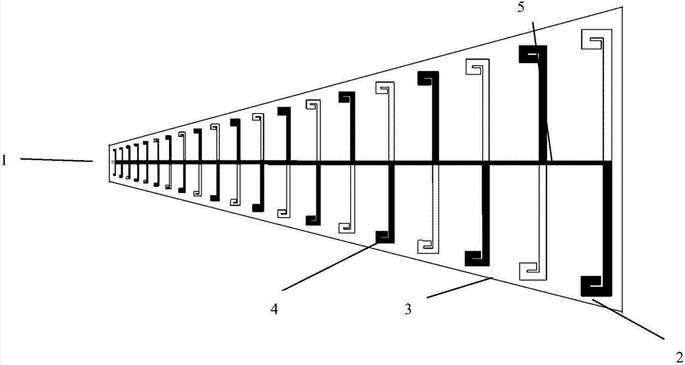
[0031] Such as Figure 1a , Figure 1b , Figure 1c Respectively shown are the top view, right view and front view of the present invention based on unit bending miniaturization printed logarithmic periodic antenna. A miniaturized printed logarithmic periodic antenna based on unit bending, including a dielectric substrate, a feed unit 1, a plurality of radiating units with different lengths, and parallel double lines 5 respectively connected to a plurality of radiating units, each radiating The unit includes a top radiation unit 2 and a bottom radiation unit 3, wherein the dielectric substrate is a printed circuit board 4;

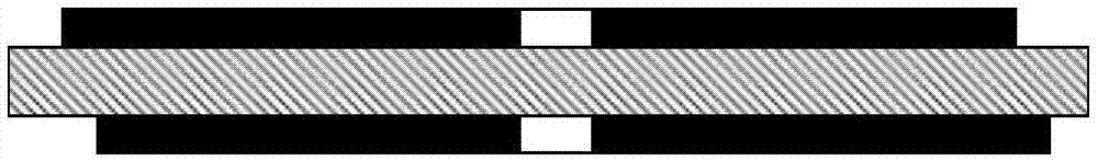
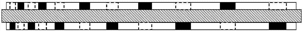
[0032] The parallel double lines are located on the upper and lower surfaces of the dielectric substrate, the radiation units are arranged on the upper and lower surfaces of the dielectric substrate in order of length, the to...


PUM


Abstract

The invention discloses a miniature printing logarithmic cycle antenna based on unit bending. The antenna comprises the components of a dielectric substrate, a feeding unit, a plurality of radiating units with different lengths, and double parallel lines which are connected with the plurality of radiating units. Each radiating unit comprises a top-layer radiating unit and a bottom-layer radiating unit. The radiating units are arranged on the upper surface and the lower surface of the dielectric substrate according to a length sequence. The top-layer radiating unit and the bottom-layer radiating unit are respectively arranged on the upper surface and the lower surface of the dielectric substrate. The dimensions and the structures of the top-layer radiating unit and the bottom-layer radiating unit in each radiating unit are same. The top-layer radiating unit and the bottom-layer radiating unit in each radiating unit are symmetrical relative to the two parallel lines. The miniature printing logarithmic cycle antenna can realize the broadband antenna with excellent matching. According to the miniature printing logarithmic cycle antenna, the transverse dimension of the antenna is greatly reduced through bending an oscillator, and furthermore antenna performance basically does not reduce, thereby realizing miniaturization of the printing logarithmic cycle antenna.

Description

technical field [0001] The invention relates to the technical field of radio frequency antennas, in particular to a miniaturized printed logarithmic periodic antenna based on unit bending. Background technique [0002] The printed logarithmic periodic dipole antenna is a frequency-invariant structure with broadband and wide-angle characteristics, and its structure is simple and easy to process. It is widely used in array antennas for radar and communication reconnaissance systems. The antenna adopts printed circuit technology, and the radiation oscillator is printed on both sides of the dielectric substrate. [0003] Since log-periodic antennas are often used for indoor distribution and elevator signal coverage, the use of log-periodic antennas is severely limited due to their large structural size, and there is a problem of large size of traditional printed log-periodic antennas. Contents of the invention [0004] The technical problem to be solved by the present inventi...

Claims


Application Information

Patent Timeline
Patent Type & Authority Applications(China)
IPC IPC(8): H01Q1/38H01Q1/50
CPCH01Q1/38H01Q1/50
Inventor 黄晓东胡阳生金秀华张闯
Owner NANJING UNIV OF POSTS & TELECOMM
Why Eureka
Try Eureka