A gap structure with multiple layers of insulating rings with large and small holes for surge protection
A technology of surge protection and gap structure, which is applied in overvoltage arresters, spark gaps, electrical components, etc. that apply spark gaps. It can solve the problem of easy carbonization of the edge of the hole, frequent actions, power system failures, and long-term reliable operation. and other problems, to achieve the effect of low cost, large economic use value and convenient processing
- Summary
- Abstract
- Description
- Claims
- Application Information
AI Technical Summary
Problems solved by technology
Method used
Image
Examples
Embodiment 1
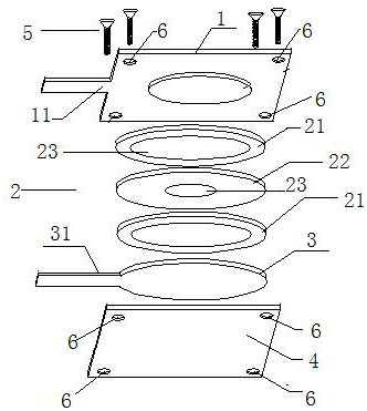
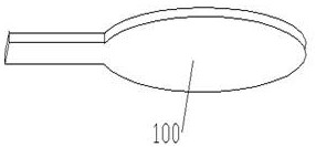
[0037] like figure 1 As shown in FIG. 6 , the present invention provides a gap structure with multi-layered large and small hole insulating rings for surge protection, which is characterized in that it includes a discharge anode 1, an insulating ring sheet group 2, a discharge anode 1, an insulating ring sheet group 2, a discharge The cathode 3, the insulating plate 4, the discharge anode 1 and the discharge cathode 3 are made of conductive material, the insulating ring sheet group 2 includes a first insulating ring sheet 21 and a second insulating ring sheet 22, the first insulating ring The sheet 21 and the second insulating ring sheet 22 are provided with through holes 23 with different diameters. The insulating plate 4 is used to fix the insulating ring sheet group 2, the discharge cathode 3 and the discharge anode 1. The discharge anode 1 And the insulating plate 4 is provided with screw holes 6, the discharge anode 1 and the insulating plate 4 are fixed together by screw...
Embodiment 2
[0049] like Figure 7 Figure 8 As shown, in this embodiment, a box body 7 is also included. The box body is composed of an upper cover 71 and a lower cover 72. The discharge anode 1, the insulating ring sheet group 2 and the Discharge cathode 3, one side of the lower cover 72 is flat, and the other side is provided with a circular or rectangular concave surface 721 for placing the discharge anode 1, the insulating ring sheet group 2 and the discharge cathode 3, the upper cover 71 And the lower cover 72 is provided with a screw hole 6, the screw 5 is arranged in the screw hole 6, the upper cover 71 and the lower cover 72 are fixed together through the screw hole 6 and the screw 5, so The insulating ring sheet group 2 includes two first insulating ring sheets 21 and one second insulating ring sheet 22, the two first insulating ring sheets 21 are installed on both sides of the one second insulating ring sheet 22, The insulating ring sheet group 2 is installed between the disch...
Embodiment 3
[0052] like Figure 9 and 10 As shown, in this embodiment, a discharge adapter plate 8 is also included, and a group of insulating ring sheet groups 9 are respectively arranged on both sides of the discharge adapter plate 8, and the insulating ring sheet group 9 includes two first insulating rings. A sheet 21 and a second insulating ring sheet 22 installed between the two first insulating ring sheets 21, the discharge adapter plate 8 and the insulating ring sheet group 2 are arranged on the discharge anode 1 between the discharge cathode 3 and the insulating plate 4 , and the insulating plate 4 and the discharge anode 1 are fixed together through screw holes 6 and screws 5 .
PUM
| Property | Measurement | Unit |
|---|---|---|
| thickness | aaaaa | aaaaa |
| thickness | aaaaa | aaaaa |
| pore size | aaaaa | aaaaa |
Abstract
Description
Claims
Application Information
 - R&D
- Intellectual Property
- Life Sciences
- Materials
- Tech Scout
- Unparalleled Data Quality
- Higher Quality Content
- 60% Fewer Hallucinations
Browse by: Latest US Patents, China's latest patents, Technical Efficacy Thesaurus, Application Domain, Technology Topic, Popular Technical Reports.
© 2025 PatSnap. All rights reserved.Legal|Privacy policy|Modern Slavery Act Transparency Statement|Sitemap|About US| Contact US: help@patsnap.com


