
Method and device for monitoring polarization mode dispersion, electronic device and storage medium

A polarization mode dispersion, monitoring signal technology, applied in the field of communications, can solve the problems of adding, monitoring sensitivity and accuracy are low, and the polarization film dispersion is not perfect, and achieves low device cost, high spectrum resource utilization, and simple monitoring device. Effect

Active Publication Date: 2017-10-20
BEIJING UNIV OF POSTS & TELECOMM
View PDF5 Cites 4 Cited by
  • Summary
  • Abstract
  • Description
  • Claims
  • Application Information

AI Technical Summary

Problems solved by technology

[0003] In the prior art, the monitoring scheme of optical fiber dispersion (CD) and optical signal-to-noise ratio (OSNR) has been relatively perfect, but the monitoring of polarizing film dispersion (PMD) is not perfect, and the main disadvantages are as follows: Adding equipment at the sending end of the signal reduces the practicability of the optical fiber communication system; or it is necessary to insert monitoring light during the transmission of the optical signal, which reduces the spectrum utilization of the optical fiber communication system; Linear Effects to Monitor Polarization Mode Dispersion
These two methods of monitoring polarization mode dispersion have the disadvantages of low monitoring sensitivity and accuracy

Method used


Image

  • Method and device for monitoring polarization mode dispersion, electronic device and storage medium
  • Method and device for monitoring polarization mode dispersion, electronic device and storage medium
  • Method and device for monitoring polarization mode dispersion, electronic device and storage medium

Examples


Embodiment Construction

[0056] The following will clearly and completely describe the technical solutions in the embodiments of the present invention with reference to the accompanying drawings in the embodiments of the present invention. Obviously, the described embodiments are only some, not all, embodiments of the present invention. Based on the embodiments of the present invention, all other embodiments obtained by persons of ordinary skill in the art without making creative efforts belong to the protection scope of the present invention.

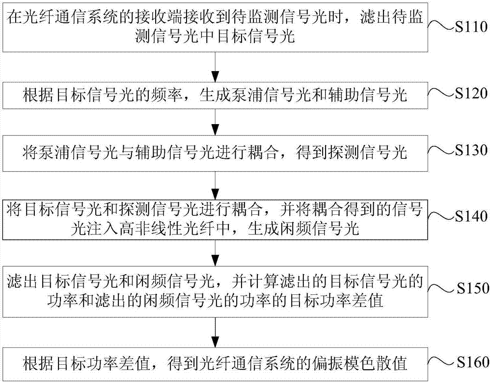
[0057] In order to improve the utilization rate and practicability of the optical fiber communication system under the premise of effectively monitoring polarization mode dispersion, the embodiments of the present invention provide a polarization mode dispersion monitoring method, device, electronic equipment and storage medium.

[0058] It should be noted that a polarization mode dispersion monitoring method and device provided by the embodiments of the presen...


PUM


Abstract

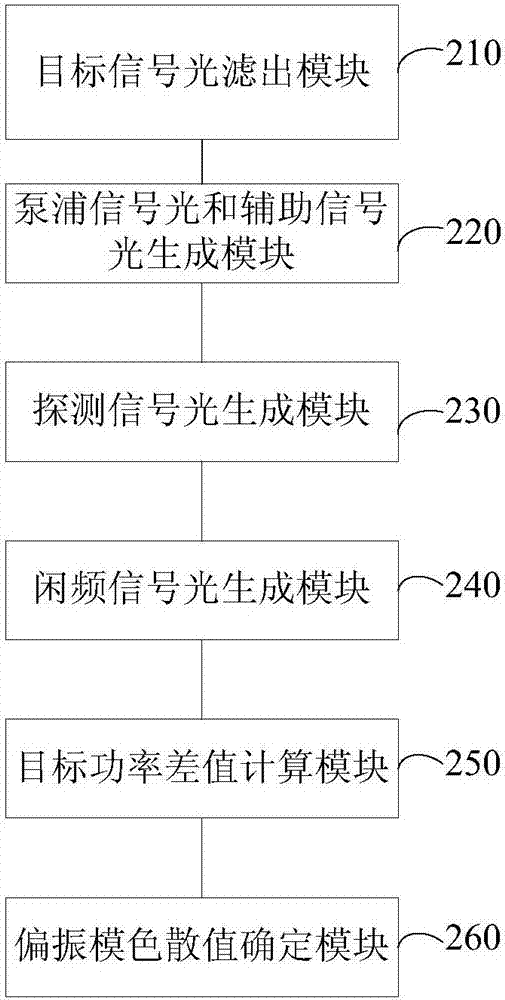
The embodiment of the invention provides a method and a device for monitoring polarization mode dispersion, an electronic device and a storage medium, applied to a receiving terminal of an optical fiber communication system. The method comprises the steps of generating pumping signal light with narrow bandwidth and low power consumption and auxiliary signal light based on the frequency of target signal light when the receiving terminal of the optical fiber communication device receives the target signal light; then coupling the pumping signal light and the auxiliary signal light to obtain detecting signal light; generating idle frequency signal light by utilizing the target signal light and the detecting signal light; and calculating a target power differential value between the power of the target signal light and the power of the idle frequency signal light so as to obtain a polarization mode dispersion value of the wireless optical fiber communication system. Through the scheme, the utilization rate and practicability of the optical fiber communication system are not only improved, but also the monitoring sensitivity and precision of the polarization mode dispersion are improved under the precondition of monitoring the polarization mode dispersion efficiently.

Description

technical field [0001] The invention relates to the technical field of communication, in particular to a polarization mode dispersion monitoring method, device, electronic equipment and storage medium. Background technique [0002] With the continuous improvement of the transmission rate of the optical fiber communication system and the continuous improvement of the transmission distance of the optical signal in the optical fiber communication system, the influence of optical fiber dispersion (CD), optical signal-to-noise ratio (OSNR), and polarization film dispersion (PMD) on the optical fiber communication system Transmission quality has a greater impact. [0003] In the prior art, the monitoring scheme of optical fiber dispersion (CD) and optical signal-to-noise ratio (OSNR) has been relatively perfect, but the monitoring of polarizing film dispersion (PMD) is not perfect, and the main disadvantages are as follows: Adding equipment at the sending end of the signal reduce...

Claims


Application Information

Patent Timeline
IPC IPC(8): H04B10/079H04B10/60
CPCH04B10/07951H04B10/60
Inventor 忻向军刘博张丽佳庄育锋王拥军张琦赵芳
Owner BEIJING UNIV OF POSTS & TELECOMM
Learn More