Time synchronization method and system

A time synchronization system and time synchronization technology, applied in time division multiplexing systems, electrical components, program control in sequence/logic controllers, etc., can solve the problem of poor operational flexibility and convenience, low reliability, and large modifications and other problems, to achieve the effect of improving authenticity and real-time performance, high operation simplicity, and improving accuracy

Active Publication Date: 2017-10-20
GUANGZHOU MINO AUTOMOTIVE EQUIP CO LTD +1
View PDF6 Cites 4 Cited by
  • Summary
  • Abstract
  • Description
  • Claims
  • Application Information

AI Technical Summary

Problems solved by technology

For the real-time and authenticity of industrial data acquisition, the prior art adopts different solutions to solve them, but there are many defects. For example: 1. Time synchronization is carried out before the PLC is used, and the PLC time and The scheme of synchronizing the standard time, but this scheme has great limitations, and the modification of the PLC is relatively large, and the operation flexibility and convenience are poor; 2. The scheme of directly reading data from the PLC is adopted, but due to the PLC The internal time is not necessarily accurate, which brings certain unreliability to the results; 3. The time stamp collected directly by the data collector during the use of the PLC is used as the PLC time, but the reliability of this solution is low , because the data collector is often unable to process data in real time, and the data accumulates in the data collector, which will cause processing lag and cannot truly realize real-time data collection

Method used


Image

  • Time synchronization method and system
  • Time synchronization method and system
  • Time synchronization method and system

Examples


Embodiment 1

[0037] Embodiment 1. A time synchronization system

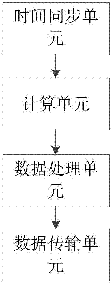
[0038] Such as figure 1 As shown, a time synchronization system, the system includes:

[0039] A time synchronization unit is used to synchronize the time of the data collector and the background server with the NTP server;

[0040] The calculation unit is used to make the data collector calculate the time difference between the network standard time synchronized from the NTP server and the time stamp data uploaded by the PLC;

[0041] The data processing unit is used to make the data collector add the time difference to the time stamp data uploaded by the PLC to obtain standardized PLC time stamp data;

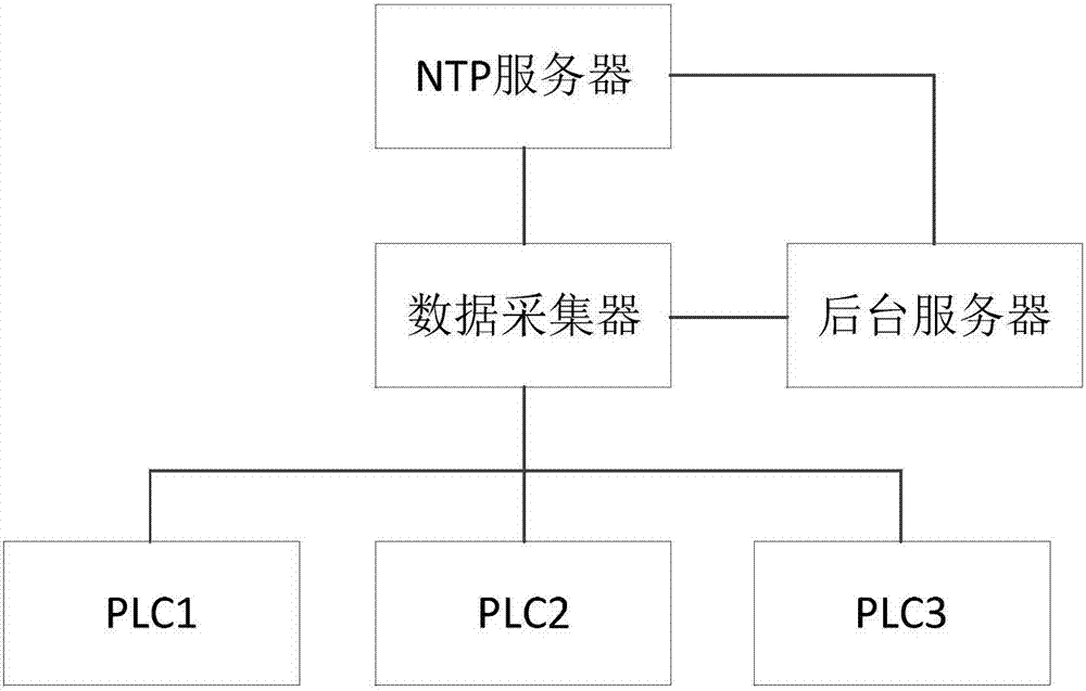
[0042] The data transmission unit is used to make the data collector transmit the standardized PLC time stamp data to the background server. It can be seen that the system structure applied by the time synchronization system of the present invention is as follows figure 2 shown.

[0043] As a preferred implementation ...

Embodiment 2

[0049] Embodiment 2, a time synchronization method

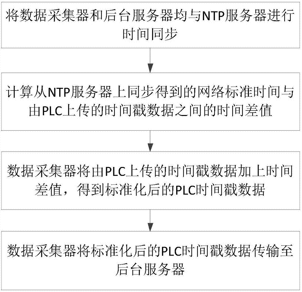
[0050] Such as image 3 Shown, a kind of time synchronization method, the steps that this method includes are:

[0051] Synchronize the time of the data collector and the background server with the NTP server;

[0052] The data collector calculates the network standard time t synchronized from the NTP server NTP with the timestamp data uploaded by the PLC t PLC The time difference between t d , ie t d = t NTP -t PLC ;

[0053] Thereafter, the PLC continuously transmits the time stamp data to the data collector, and the data collector will upload the time stamp data t PLC_n plus the time difference t d , get the standardized PLC time stamp data t real , ie t real = t PLC_n +t d ;

[0054] The data collector transmits the standardized PLC time stamp data to the background server for further data processing.

[0055] As a preferred implementation of the method embodiment, the data collector transmits the standard...

Embodiment 3

[0066] Embodiment 3, a specific embodiment of a time synchronization method

[0067] In this embodiment, the PLC is set to include PLC1, PLC2, and PLC3, and the current time is 14:15:27 on January 9, 2017, the time of PLC1 is 14:14:00 on January 9, 2017, and the time of PLC2 is January 8, 2017 14:15:27, and PLC3 time is January 1, 1970 14:15:27.

[0068] A time synchronization method, its specific steps include:

[0069] S101, the data collector and the background server are all synchronized with the NTP server in the form of Ethernet, so that the data collector and the background server are all synchronized to obtain the network standard time from the NTP server, that is, at this time, the data collector, the background The time of the server and the NTP server is synchronized, and the current time is 14:15:27 on January 9, 2017;

[0070] S102, the data collector will carry out the data format conversion of Unix timestamp (00:00 on January 1, 1970, Greenwich Mean Time) from...


PUM


Abstract

The present invention discloses a time synchronization method and system. The system includes a time synchronization unit, a calculation unit, a data processing unit and a data transmission unit. The method comprises the following steps: a data collector and a background server are time-synchronized with an NTP server; the time difference between the network standard time synchronized by the NTP server and the time-stamped data uploaded by a PLC is calculated; afterwards, the data collector adds the time difference to the time-stamped data uploaded by the PLC to obtain standardized PLC time stamp data, and uploads the standardized PLC time stamp data to the background server. By using the method and the system of the present invention, the time synchronization between the PLC, the data collector and the backstage server can be quickly and easily realized, real-time real data collection of the industrial data can be realized, the accuracy of subsequent industrial data processing results can be greatly improved, modification of the PLC is not required, and the high convenience is achieved. The time synchronization method and system can be widely applied in the field of industrial data acquisition.

Description

technical field [0001] The invention relates to time synchronization technology, in particular to a time synchronization method and system applicable to PLC, data collector and background server. Background technique [0002] Explanation of technical terms: [0003] NTP server: Network Time Protocol (NTP), that is, network time server. [0004] The real-time collection of industrial data has become the basic support of industrial informatization. Among them, there are higher requirements for the authenticity and real-time performance of industrial data. For the real-time and authenticity of industrial data acquisition, the prior art adopts different solutions to solve them, but there are many defects. For example: 1. Time synchronization is carried out before the PLC is used, and the PLC time and The scheme of synchronizing the standard time, but this scheme has great limitations, and the modification of the PLC is relatively large, and the operation flexibility and conve...

Claims


Application Information

Patent Timeline
IPC IPC(8): H04J3/06G05B19/05
CPCG05B19/05H04J3/0647
Inventor 陈旻琪贺毅王斌邓荣龙姚维兵
Owner GUANGZHOU MINO AUTOMOTIVE EQUIP CO LTD
Why Eureka
Try Eureka