Exchange table device for machine tool
A technology for exchange tables and machine tools, applied in metal processing machinery parts, large fixed members, metal processing equipment, etc., can solve the problems of inability to improve the efficiency of machine tools, high costs, etc., to reduce labor management costs, save time for workpiece replacement, Universal effect
- Summary
- Abstract
- Description
- Claims
- Application Information
AI Technical Summary
Problems solved by technology
Method used
Image

Examples
Embodiment 1
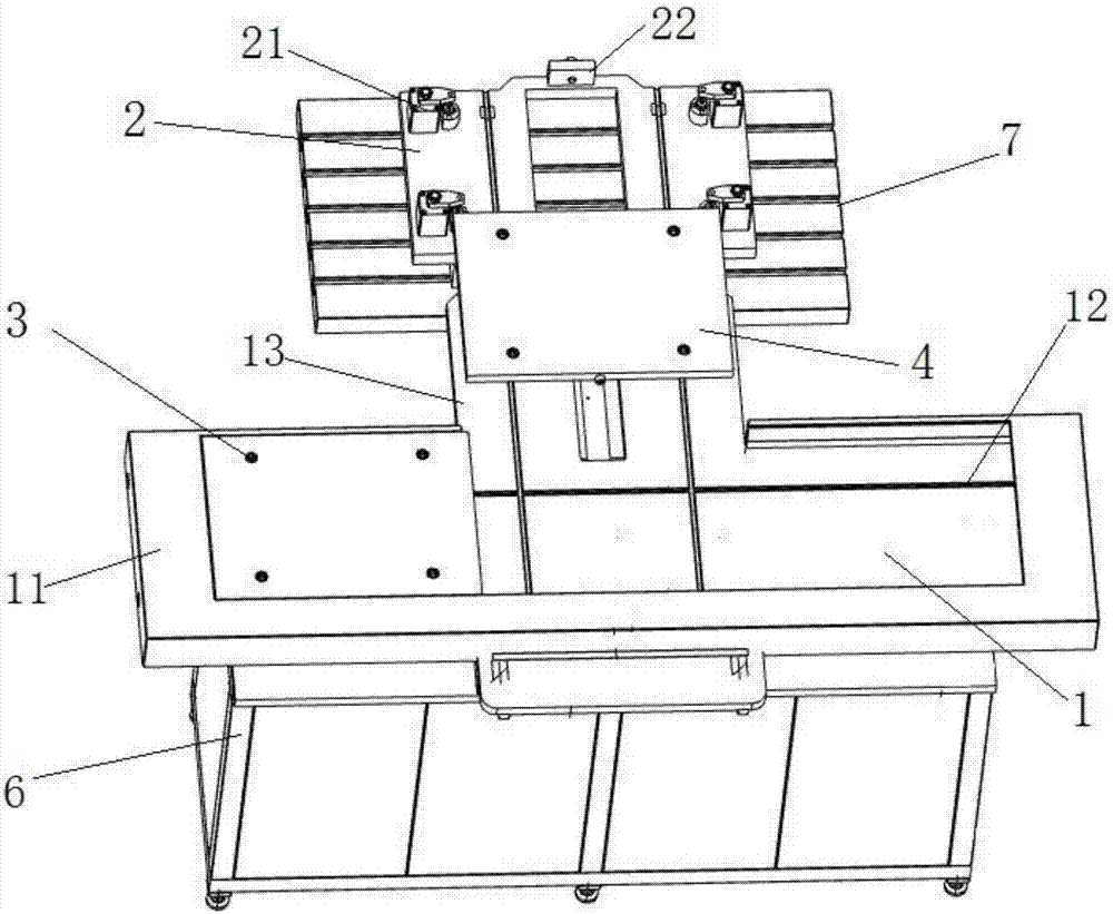
[0040] like figure 1 As shown, it is a structural diagram of a switchboard device for a machine tool according to the present invention, and the device includes a moving frame 1 , a positioning plate 2 and a control cabinet 6 . The moving frame 1 is installed on the control cabinet 6, and the positioning plate 2 is installed on the workbench 7 of the machine tool machining center. Two exchange trays are installed in the mobile frame 1, which are respectively a left exchange tray 3 and a right exchange tray 4, and the structures of the two exchange trays are the same. The control cabinet 6 provides power for the device and controls the operation of the device.
[0041] The surface of the moving frame 1 is provided with guide grooves 12 parallel to the X-axis and Y-axis directions of the machine tool, and the exchange tray can move along the guide grooves 12 . The left exchange tray 3 can move in the space on the left side of the moving frame 1 along the direction parallel to ...
Embodiment 2
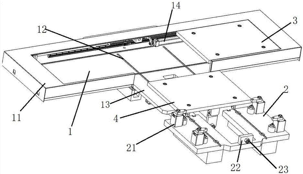
[0046] combine Figure 4 and Figure 5 As shown, in this embodiment, on the basis of the above facts, two protruding guide plates 13 are provided in the middle of the moving frame 1 for connecting with the positioning plate 2 . A line rail 14 is installed in the frame 11 of the moving frame 1 for controlling the movement of the exchange pallet along the X-axis parallel direction of the machine tool. Two moving blocks are installed on the line track 14, respectively a left moving block 15 and a right moving block 16, which are respectively used to connect the left switching tray 3 and the right switching tray 4, and the moving block is provided with a draw-in slot. Limiting blocks 17 are provided at both ends of the line track 14 for limiting the moving distance of the moving block.
[0047] exist Figure 4 In this state, the line rail 1 is located at the left end of the mobile frame 1 and is in contact with the left limit block 17. The left moving block 15 is connected with...
Embodiment 3
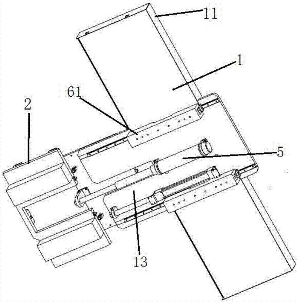
[0049] combine figure 2 and Figure 5 As shown, this implementation is based on the above-mentioned embodiments. An oil cylinder 5 is installed at the bottom of the moving frame 1 for controlling the movement of the exchange tray along the Y-axis parallel direction of the machine tool. The position of the oil cylinder 5 is between the two guide plates 13 .
[0050] combine Image 6 As shown, the oil cylinder 5 includes a cylinder liner and an oil cylinder rod 51, and an oil cylinder block 52 is installed at the front end of the oil cylinder rod 51 for connecting with the exchange tray. When the exchange tray is located in the middle of the mobile frame 1, it is connected with the oil cylinder 5. The extension of the oil cylinder rod 51 pushes the exchange tray to move towards the positioning plate 2, and the retraction of the oil cylinder rod 51 pulls and moves towards the mobile frame 1.
PUM
 Abstract
Description
Claims
Application Information
 - R&D
- Intellectual Property
- Life Sciences
- Materials
- Tech Scout
- Unparalleled Data Quality
- Higher Quality Content
- 60% Fewer Hallucinations
Browse by: Latest US Patents, China's latest patents, Technical Efficacy Thesaurus, Application Domain, Technology Topic, Popular Technical Reports.
© 2025 PatSnap. All rights reserved.Legal|Privacy policy|Modern Slavery Act Transparency Statement|Sitemap|About US| Contact US: help@patsnap.com