Magnetically driven mini-sized underwater robot and control method thereof

A magnetic drive and robotic technology, applied in the field of robotics, to achieve the effects of reducing interference, flexible and convenient use, and novel control methods

Inactive Publication Date: 2017-10-24
MAANSHAN FULAIYI ENVIRONMENT PROTECTION TECH CO LTD
View PDF6 Cites 5 Cited by
  • Summary
  • Abstract
  • Description
  • Claims
  • Application Information

AI Technical Summary

Problems solved by technology

[0006] In view of the small power provided by the power components of the existing small-volume underwater robot, which cannot meet the needs of use in relatively deep waters, and the problem of large volume caused by the direction control mechanism, the present invention provides a magnetically driven miniature underwater robot and its control method. When the current flows to the coil, the

Method used


Image

  • Magnetically driven mini-sized underwater robot and control method thereof
  • Magnetically driven mini-sized underwater robot and control method thereof
  • Magnetically driven mini-sized underwater robot and control method thereof

Examples


Embodiment 1

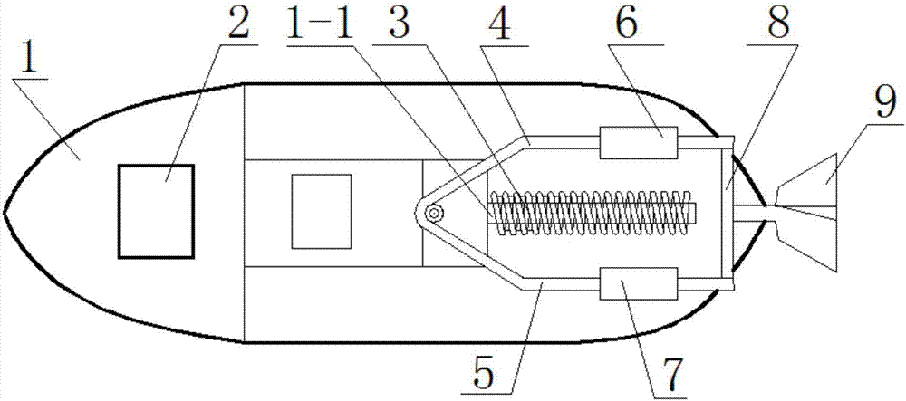
[0041] Such as figure 1 , figure 2 , image 3 As shown, the magnetically driven miniature underwater robot of the present invention includes a body 1 and a fishtail drive assembly. The fishtail drive assembly includes at least one coil 3 and a tail swing mechanism. The tail swing mechanism has a pair of opposite magnetic blocks with opposite polarities. The coil 3 is energized to attract or repel the magnetic block to provide power for the tail swing mechanism.

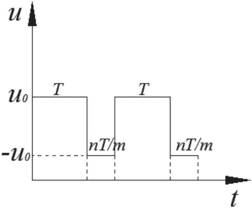
[0042] The present invention uses the coil 3 to cooperate with the magnetic block. When the current flows to the coil 3, the generated magnetic field interacts with the magnetic field of the magnetic block. One side generates suction force, and the other side generates thrust force. When the current direction changes, The direction of the force also changes accordingly, thereby pushing the tail to produce a swinging effect, and then pushing the whole body forward, while changing the power-on time to realize directi...

Embodiment 2

[0049] Such as Figure 4 As shown, the magnetic drive type underwater robot of the present embodiment, on the basis of embodiment 1, the central axis of the coil 3 is perpendicular to the upper magnetic block 6 or the lower magnetic block 7, because the magnetic properties of the coil 3 at two stages are the largest, it can Increase the swing force of empennage 9, thereby increase the propulsion of robot.

Embodiment 3

[0051] Such as Figure 5 As shown, the magnetic drive type underwater robot of the present embodiment, on the basis of Embodiment 1, the number of coils 3 is three, and three coils 3 are arranged in parallel, and one of the coils 3 is located at the upper magnetic block 6 and the lower magnetic block 7, one coil 3 is located outside the upper magnetic block 6, and one coil 3 is located outside the lower magnetic block 7. Three coils 3 are used to realize the control of the upper magnetic block 6 and the lower magnetic block 7, thereby further increasing the size of the empennage. 9 swing force, so as to increase the propulsion of the robot. This method can be used when the robot has a large load or needs to swim quickly, and the robot volume is not required.


PUM


Abstract

The invention discloses a magnetically driven miniature underwater robot and a control method thereof, belonging to the technical field of robots. It includes a body and a fishtail drive assembly, the fishtail drive assembly includes at least one coil and a tail swing mechanism, the swing tail mechanism has a pair of magnets with opposite polarities on opposite sides, and the coils are energized to attract or repel the magnets, which is the pendulum The tail mechanism provides power. The present invention adopts the cooperation between the coil and the magnetic block. When the current flows to the coil, the generated magnetic field interacts with the magnetic field of the magnetic block. One side generates suction force, and the other side generates thrust force. When the current direction changes, the force The direction is also changed accordingly, thereby pushing the tail to produce a swinging effect, and then pushing the whole body forward. At the same time, the power-on time is changed to realize the control of the direction, which has the advantages of simple structure, reasonable design and easy manufacture.

Description

technical field [0001] The invention belongs to the technical field of robots, and more specifically relates to a magnetically driven miniature underwater robot and a control method thereof. Background technique [0002] With the development of human civilization, the land resources that can be mined and utilized are decreasing and exhausted day by day. The ocean area accounts for 71% of the earth's area. The ocean is rich in biological resources and mineral resources. The pace of human development and utilization of the ocean is gradually accelerating with the development of science and technology. At the same time, the development of marine environment monitoring technology is of great significance to many aspects such as protecting the marine environment, developing marine resources, safeguarding national marine rights and interests, enhancing national marine scientific research strength, and developing the national economy. As ocean development activities become more fr...

Claims


Application Information

Patent Timeline
IPC IPC(8): B63H1/36B63H23/22
CPCB63H1/36B63H23/22
Inventor 王明明刘鹏
Owner MAANSHAN FULAIYI ENVIRONMENT PROTECTION TECH CO LTD
Why Eureka
Try Eureka