Filling discharge device

A discharge device and a technology for loading and discharging materials, which are applied in packaging, mixers with rotating stirring devices, liquid materials, etc., can solve the problems of low filling efficiency

Inactive Publication Date: 2017-10-24
江苏首达机械有限公司
View PDF7 Cites 2 Cited by
  • Summary
  • Abstract
  • Description
  • Claims
  • Application Information

AI Technical Summary

Problems solved by technology

When filling materials with high viscosity, the general method is to extend the filling time to ensure that the filling volume reaches the bottle body standard. This way makes the filling efficiency relatively low

Method used


Image

  • Filling discharge device
  • Filling discharge device
  • Filling discharge device

Examples


Embodiment Construction

[0014] In order to make the above objects, features and advantages of the present invention more comprehensible, specific implementations of the present invention will be described in detail below in conjunction with the accompanying drawings. In the following description, numerous specific details are set forth in order to provide a thorough understanding of the present invention. However, the present invention can be implemented in many other ways different from those described here, and those skilled in the art can make similar improvements without departing from the connotation of the present invention, so the present invention is not limited by the specific embodiments disclosed below.

[0015] It should be noted that when an element is referred to as being “fixed” to another element, it can be directly on the other element or there can also be an intervening element. When an element is referred to as being "connected to" another element, it can be directly connected to t...


PUM


Abstract

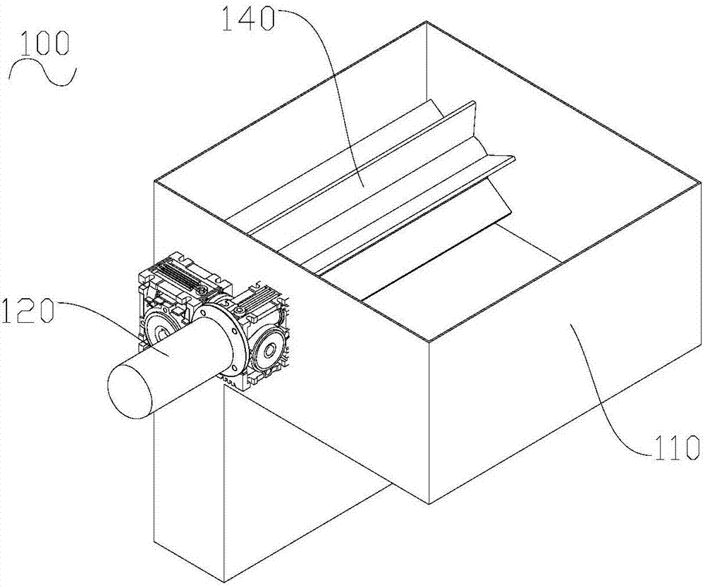
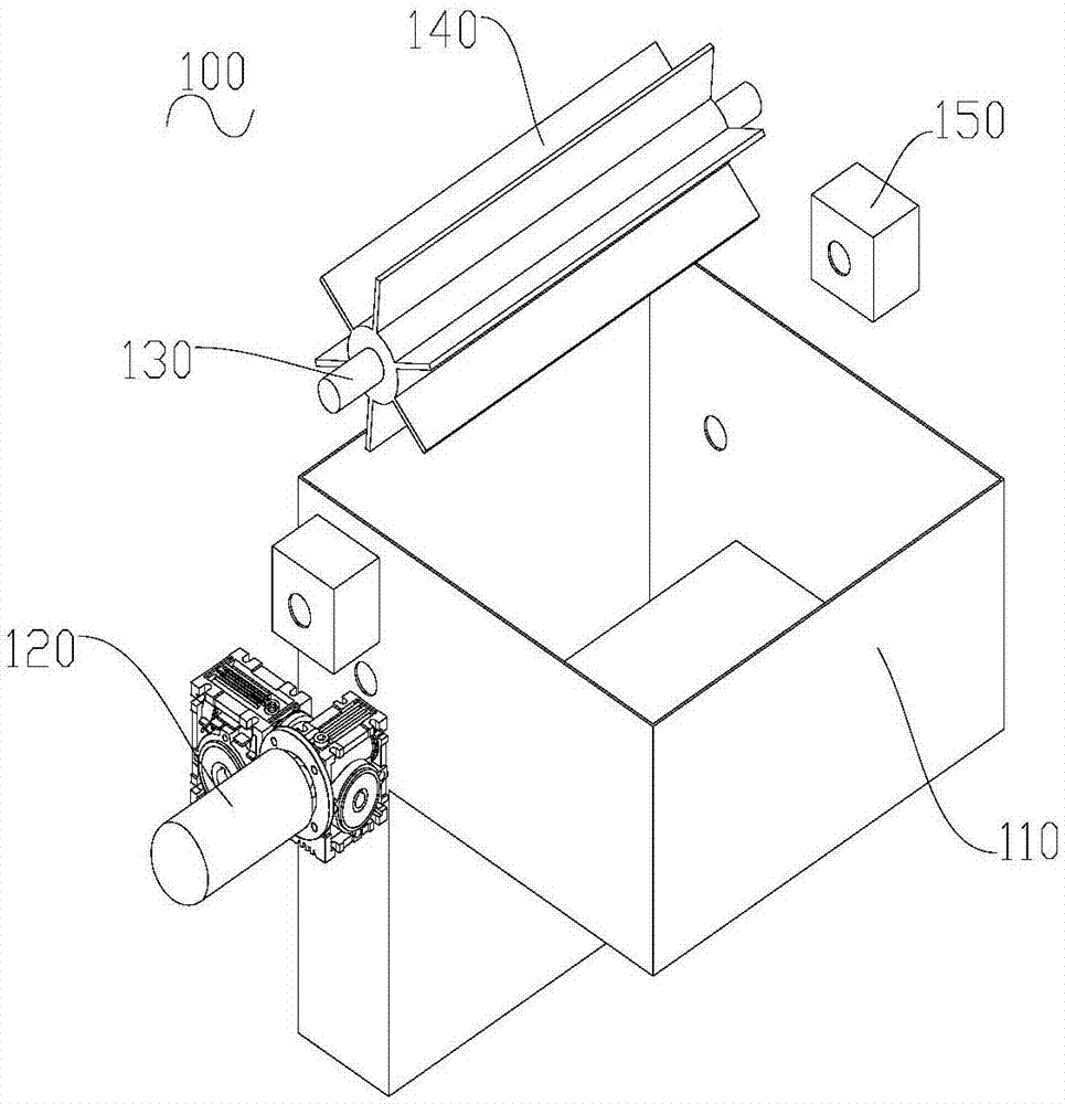
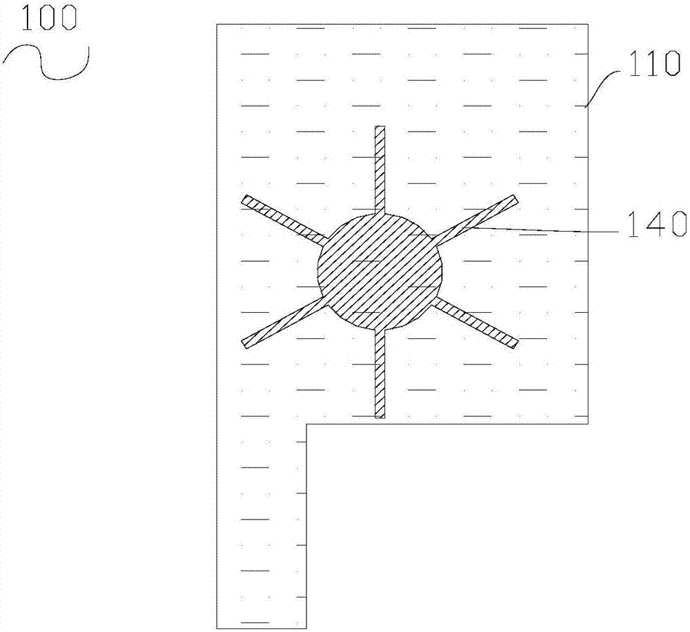
The invention relates to a filling discharge device. The filling discharge device comprises a tank, and a stirring device mounted in the tank. The stirring device comprises a rotating shaft, and multiple stirring blades mounted on the rotating shaft and uniformly distributed in the peripheral direction. Each stirring blade extends to the inner wall of the tank in the axial direction of the rotating shaft. When materials with high viscosity are filled, the stirring device works, so that the materials reach a certain initial velocity, the discharge speed is accelerated, the filling time is shortened, and the filling discharge device is higher in filling efficiency.

Description

technical field [0001] The invention relates to a filling and discharging device. Background technique [0002] People often use a variety of bottled daily necessities in daily life, such as bottled mineral water, bottled shampoo, bottled beverages, etc., and need to use a filling machine to fill the bottle body. Generally, a piston filling machine is used to fill the bottle body, and the piston reciprocates up and down to perform suction and discharge, and finally the bottle body is filled through the filling head. [0003] In unit time, the amount of material with high viscosity flowing into the bottle is less than that of material with low viscosity flowing into the bottle. When filling materials with high viscosity, the general method is to extend the filling time to ensure that the filling volume reaches the bottle body standard. This way makes the filling efficiency relatively low. Contents of the invention [0004] The technical problem to be solved by the present...

Claims


Application Information

Patent Timeline
Patent Type & Authority Applications(China)
IPC IPC(8): B65B3/04B01F7/04
CPCB65B3/04B01F27/70
Inventor 孙步达丁守央丁振庭
Owner 江苏首达机械有限公司
Why Eureka
Try Eureka