
An electronic expansion valve

An electronic expansion valve and valve seat technology, which is applied in the field of solenoid valves, can solve the problems of eliminating or reducing noise, electronic expansion valve noise, and the inability to improve the electronic expansion valve, etc., to achieve the effect of reducing noise and weakening the impact force

Active Publication Date: 2020-09-29
ZHEJIANG DUNAN ARTIFICIAL ENVIRONMENT
View PDF2 Cites 0 Cited by
  • Summary
  • Abstract
  • Description
  • Claims
  • Application Information

AI Technical Summary

Problems solved by technology

However, when the refrigerant is running unstable, the electronic expansion valve will produce noise
Since the noise is only generated when the electronic expansion valve is working, and the noise does not exist all the time, the reason for the noise cannot be found for a long period of time, and the electronic expansion valve cannot be further improved to eliminate or reduce the noise.

Method used


Image

  • An electronic expansion valve
  • An electronic expansion valve
  • An electronic expansion valve

Examples


Embodiment 1

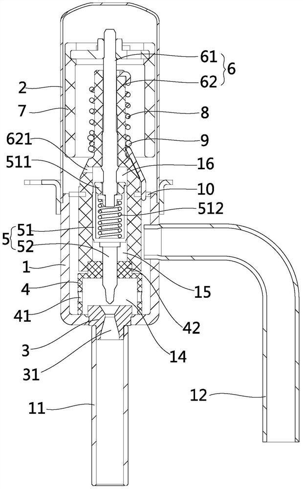
[0030] Such as figure 1 As shown, the electronic expansion valve in this embodiment includes a valve seat 1, a sleeve 2, a valve port seat 3, a guide sleeve 4, a valve needle 5 and a nut assembly 6. The valve seat 1 is provided with an inlet and an outlet, and the inlet is connected with In the intake pipe 12, the valve port seat 3 is provided with a valve port 31, and the valve port seat 3 is installed on the outlet, and an outlet pipe 11 is also connected at the outlet, and the intake pipe 11 communicates with the valve port 31. The nut assembly 6 includes a screw 61 and a nut 62. The nut 62 is a resin piece. The screw 61 is screwed into the nut 62. The outer side wall of the nut 62 is provided with a connecting piece 10, and the connecting piece 10 is welded and fixed to the inner wall of the valve seat 1. The valve needle 5 includes a large-diameter section 51 and a small-diameter section 52. The large-diameter section 51 is located in the inner cavity of the nut 62 and is s...

Embodiment 2

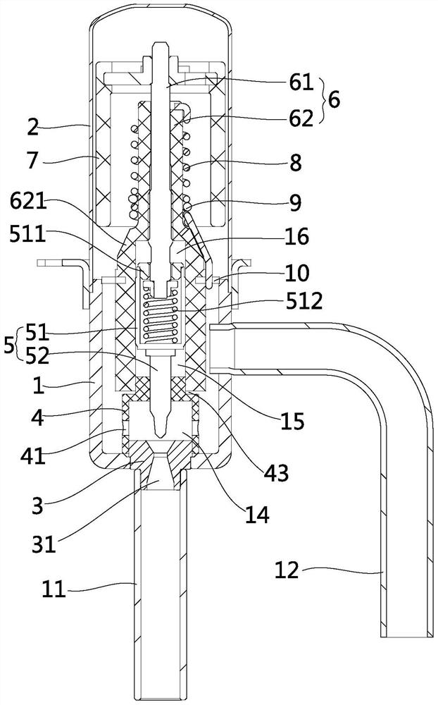
[0038] Such as figure 2 As shown, the difference from the first embodiment is that the upper end of the guide sleeve 4 in this embodiment is provided with a positioning step 43. When installed at room temperature, there is a certain gap between the horizontal plane of the positioning step 43 and the lower end surface of the nut 62 , The vertical surface of the positioning step 43 abuts against the inner ring surface of the nut 62, so that the nut 62 plays an internal guiding role for the guide sleeve 4. The inner side of the lower end of the guide sleeve 4 abuts the outer side of the valve port seat 3, so that the valve port seat 3 The guide sleeve 4 plays an external guiding role. Under the action of high temperature or fluid medium, the horizontal surface of the positioning step 43 abuts against the lower end surface of the nut 62, which further plays a role of limiting. Therefore, the installation method of the guide sleeve 4 in this embodiment can further improve the coaxia...

Embodiment 3

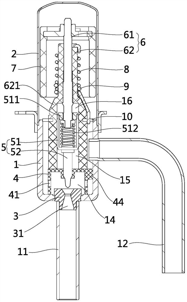
[0040] Such as image 3 As shown, the difference from the second embodiment is that the upper end surface of the guide sleeve 4 in this embodiment abuts against the lower end surface of the nut 62, and the side wall of the guide sleeve 4 is provided with a plurality of positioning blocks 44 at intervals in the circumferential direction. The outer side of the valve seat abuts the inner side wall of the valve seat 1, and the valve seat 1 realizes the outer guidance of the guide sleeve 4, which ensures the coaxiality of the valve needle 5, the nut 62 and the guide sleeve 4, and reduces the guide sleeve 4 in the high temperature environment. The deformation of the valve pin 5 and the nut 62 affect the clearance.


PUM


Abstract

The invention discloses an electronic expansion valve and belongs to the technical field of solenoid valves. The technical problem that noise is produced due to violent vibration of a valve needle in the prior art is solved. The electronic expansion valve comprises a valve seat and a drive device. A valve opening seat, a guide sleeve, a valve needle and a nut assembly are installed in the valve seat. The nut assembly comprises a nut and a screw. The drive device is used for driving the screw to move axially. The valve needle is connected with the screw and is driven by the screw to reciprocate in the axial direction so as to adjust the opening degree of the valve opening seat. The valve needle comprises a large diameter section and a small diameter section. The large diameter section is connected with the screw and slides in the nut axially. The upper portion of the guide sleeve abuts against the lower end of the nut. The lower end of the guide sleeve abuts against the bottom wall of the valve seat. The small diameter section is sleeved with the guide sleeve and is connected with the guide sleeve in a sliding fit mode. The side wall of the guide sleeve is provided with a radial through hole.

Description

【Technical Field】 [0001] The present invention relates to the technical field of solenoid valves, in particular to an electronic expansion valve used in refrigeration systems such as air conditioners and refrigerators. 【Background technique】 [0002] The electronic expansion valve is an important part of the refrigeration system, which mainly plays the role of throttling, reducing pressure and adjusting flow. The existing electronic expansion valve includes a valve body, a nut, and a valve needle assembly that is threadedly fitted with the nut. A drive device is used to drive the valve needle assembly to rotate while generating axial movement to adjust the valve opening to achieve flow control. [0003] The invention patent with the publication number CN102454818A and the name "an electric valve" discloses an electronic expansion valve with the following structure: valve seat, valve core seat, valve needle screw assembly, nut, wherein the valve needle screw assembly is installed on...

Claims


Application Information

Patent Timeline
Patent Type & Authority Patents(China)
IPC IPC(8): F16K1/32F16K1/38F16K47/08F16K31/50
CPCF16K1/32F16K1/385F16K31/50F16K47/08
Inventor 王定军苏鹏朱方英
Owner ZHEJIANG DUNAN ARTIFICIAL ENVIRONMENT
Learn More