Positioning system, and synchronous controller networking system of positioning system

A technology of synchronous controller and positioning system, applied in the field of positioning, can solve the problems of high cost and difficult coverage of positioning base stations, and achieve the effects of saving costs, improving transmission reliability, and reducing system complexity

Active Publication Date: 2017-10-24
KUNCHEN TECH CO LTD
View PDF7 Cites 6 Cited by
  • Summary
  • Abstract
  • Description
  • Claims
  • Application Information

AI Technical Summary

Problems solved by technology

In the prior art, there are mainly two commonly used synchronization methods between positioning base stations. One is that each positioning base station contains an accurate synchronization clock, such as an atomic clock. This method is expensive and needs to be regularly checked. Clock verification; the second is to transmit synchronization signals between positioning base stations. The synchronization signals in this method are usually generated by the synchronization controller, but in actual application scenarios, when the number of positioning base stations included in the positioning system is large, one It is difficult for the synchronization controller to cover all the positioning base stations

Method used


Image

  • Positioning system, and synchronous controller networking system of positioning system
  • Positioning system, and synchronous controller networking system of positioning system
  • Positioning system, and synchronous controller networking system of positioning system

Examples


Embodiment Construction

[0010] Specific embodiments of the present invention will be described in detail below, and it should be noted that the embodiments described here are only for illustration, not for limiting the present invention. In the following description, numerous specific details are set forth in order to provide a thorough understanding of the present invention. It will be apparent, however, to one of ordinary skill in the art that these specific details need not be employed to practice the present invention. In other instances, well-known circuits, materials or methods have not been described in detail in order to avoid obscuring the present invention.

[0011] Throughout this specification, reference to "one embodiment," "an embodiment," "an example," or "example" means that a particular feature, structure, or characteristic described in connection with the embodiment or example is included in the present invention. In at least one embodiment. Thus, appearances of the phrases "in on...


PUM


Abstract

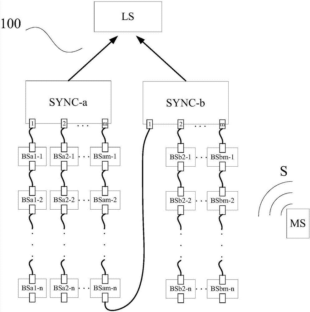
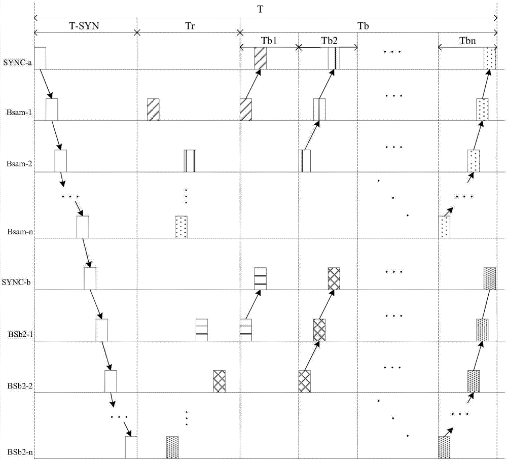
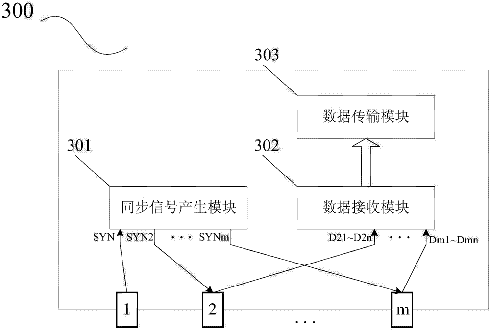
The invention discloses a synchronous controller networking system of a positioning system. The synchronous controller networking system comprises a first synchronous controller, a first set of positioning base station groups, a second synchronous controller, and a second set of positioning base station groups. A first positioning base station in each positioning base station group of the first set of positioning base station groups is coupled to the corresponding interface of the first synchronous controller so as to receive a synchronization signal and send the received synchronization signal to positioning base stations of the above positioning base station group. The second synchronous controller is coupled to the first synchronous controller or any one positioning base station in the first set of positioning base station groups so as to receive the synchronization signal. A first positioning base station in each positioning base station group of the second set of positioning base station groups is respectively coupled to the second synchronous controller to receive the synchronization signal. According to the invention, the positioning system of the present invention may contain a large number of positioning base stations, so that the expansion of a to-be-positioned area can be realized. The hierarchical cascade is realized by adopting synchronous controllers, so that the data returning period is shortened. The positioning real-time property is improved.

Description

technical field [0001] The present disclosure relates to wireless communications, and more particularly, the present disclosure relates to the field of positioning. Background technique [0002] With the rapid increase of data services and multimedia services, on the basis of short-distance high-speed wireless communication, people's demand for location information awareness is also increasing. Especially in complex environments, such as airport halls, exhibition halls, warehouses, supermarkets, libraries, underground parking lots, mines, etc., or environments that require special requirements for personnel positioning, such as prisons, kindergartens, hospitals, nursing homes, etc., often require Determine the location information of mobile terminals or their holders, facilities and objects, and then use them for monitoring and management, security alarms, command and dispatch, logistics, telemetry and remote control, and emergency rescue. [0003] Commonly used positioning...

Claims


Application Information

Patent Timeline
Patent Type & Authority Applications(China)
IPC IPC(8): H04W64/00H04J3/06
CPCH04J3/0638H04W64/006
Inventor 陈伟陈跃东代江张晨曦李飞雪
Owner KUNCHEN TECH CO LTD
Why Eureka
Try Eureka