Thermal protection system reducing hypersonic speed aerodynamic heat

A thermal protection structure, rapid aerodynamic heat technology, applied in aircraft parts, attack equipment, projectiles, etc., to achieve the effect of lightweight heat protection structure, reduce weight, and reduce manufacturing costs

Inactive Publication Date: 2017-10-27
HARBIN INST OF TECH
View PDF5 Cites 1 Cited by
  • Summary
  • Abstract
  • Description
  • Claims
  • Application Information

AI Technical Summary

Problems solved by technology

[0003] The local heat flow on the surface of the aircraft increases with the increase of the surface curvature, so the current heat protection structure, such as the bottom heat shield of the spacecraft return module and the design of the nose cone of the missile, adopts a smooth shape to make the surface of the heat protection structure more heated Uniform, and prevent local overheating, but the entire surface of the structure is exposed to high-velocity air flow and subjected to more severe aerodynamic heating

Method used


Image

  • Thermal protection system reducing hypersonic speed aerodynamic heat
  • Thermal protection system reducing hypersonic speed aerodynamic heat
  • Thermal protection system reducing hypersonic speed aerodynamic heat

Examples


specific Embodiment approach 1

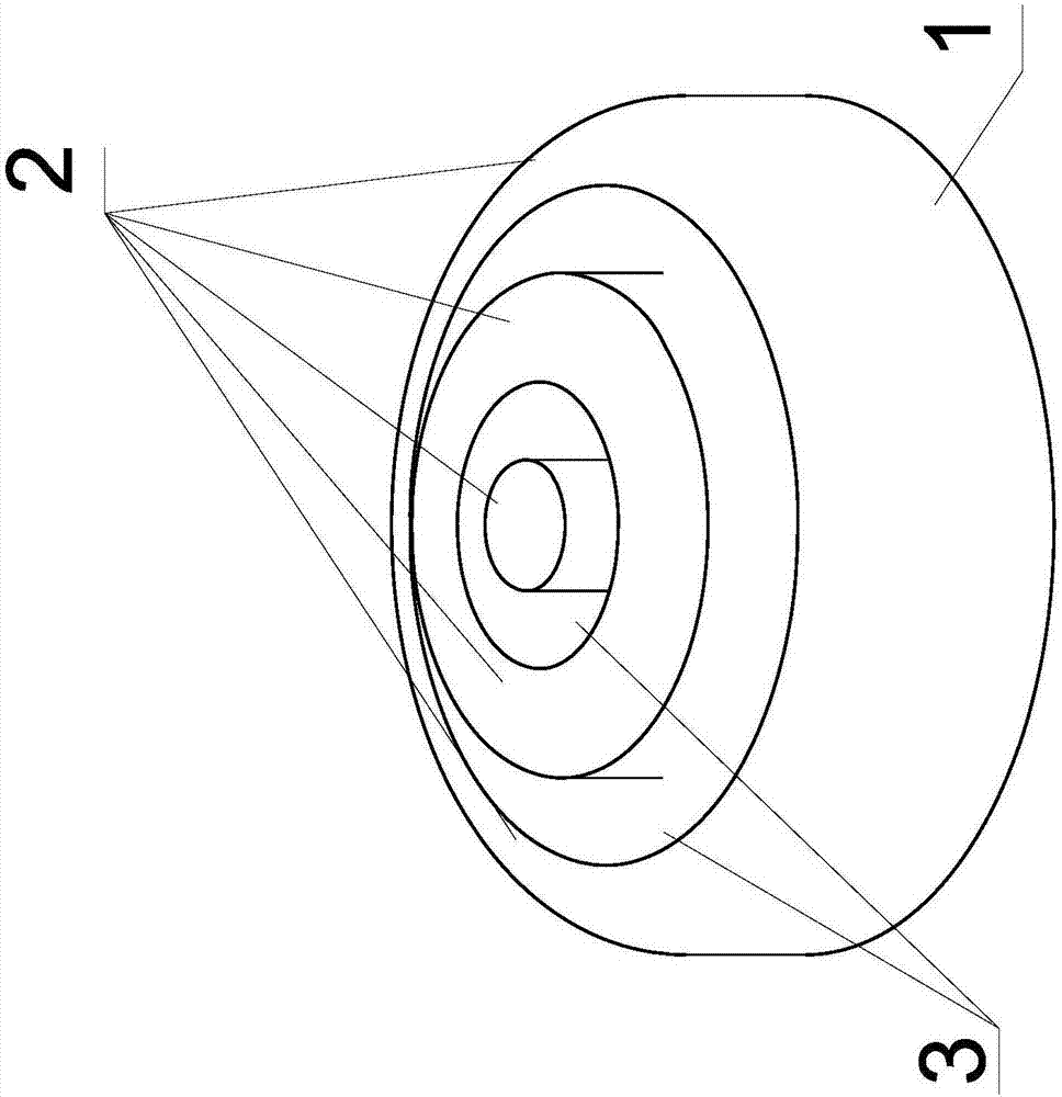
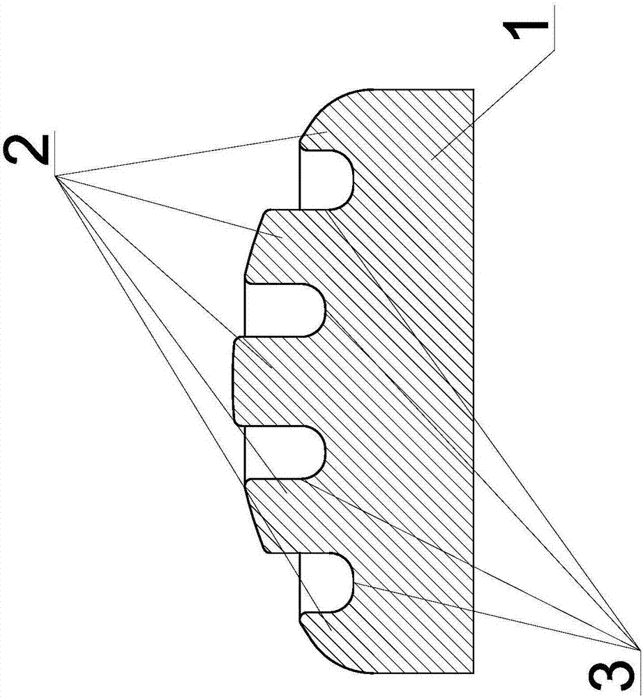
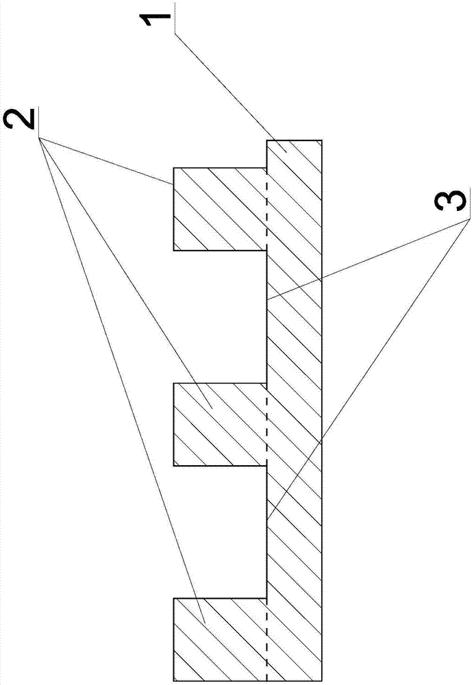
[0013] Specific implementation mode one: combine Figure 1-Figure 7 This embodiment is described. This embodiment describes a thermal protection structure for reducing hypersonic aerodynamic heat, which includes a base 1 on which a plurality of protrusions 2 are processed, and a plurality of grooves are formed between the plurality of protrusions 2 Slot 3.

specific Embodiment approach 2

[0014] Specific implementation mode two: combination Figure 1-Figure 7 Describe this embodiment, a thermal protection structure for reducing hypersonic aerodynamic heat in this embodiment, the base 1 is made of graphite-based dissipative heat-resistant material, so the protrusion 2 is also made of graphite-based dissipative heat-resistant raised material. Others are the same as in the first embodiment.

specific Embodiment approach 3

[0015] Specific implementation mode three: combination Figure 1-Figure 5 This embodiment is described. This embodiment describes a thermal protection structure for reducing hypersonic aerodynamic heat. The ratio of the width of each groove 3 to the groove depth is greater than 0.8 and less than 5. Others are the same as in the first embodiment.


PUM


Abstract

The invention relates to a thermal protection system reducing hypersonic speed aerodynamic heat, and relates to a thermal protection system. In order to get rid of a design method of a conventional thermal protection system that in order to protect materials, local aerodynamic heat is reduced. The thermal protection system comprises a base, wherein a plurality of protrusions are processed on the base; and grooves are respectively formed in every two adjacent protrusions. The thermal protection system disclosed by the invention is used for the field of aerospace hypersonic speed thermal protection.

Description

technical field [0001] The invention relates to a thermal protection structure, in particular to a thermal protection structure for reducing hypersonic aerodynamic heat. Background technique [0002] When spacecraft return capsules, aerospace planes, missiles and other aircraft fly at hypersonic speeds in the atmosphere, the surrounding atmosphere is subjected to intense compression and friction to heat up, and the heat is mainly transferred to the surface of the aircraft through convection. The main purpose of a thermal shielding structure is to block the flow of heat to prevent the aircraft structure behind it from heating up and failing. [0003] The local heat flow on the surface of the aircraft increases with the increase of the surface curvature, so the current heat protection structure, such as the bottom heat shield of the spacecraft return module and the design of the nose cone of the missile, adopts a smooth shape to make the surface of the heat protection structur...

Claims


Application Information

Patent Timeline
Patent Type & Authority Applications(China)
IPC IPC(8): B64C1/38F42B15/34
CPCB64C1/38F42B15/34
Inventor 武睿武高辉马元宏
Owner HARBIN INST OF TECH
Why Eureka
Try Eureka