Hydraulic cylinder mechanical locking device, mechanically-locked hydraulic cylinder and locking method of hydraulic cylinder

A hydraulic cylinder and mechanical locking technology, which is applied in the direction of fluid pressure actuating devices, etc., can solve the problems of low load bearing capacity, easily damaged seal, and high unlocking pressure, and achieve uniform unlocking pressure, stable oil pressure, and low unlocking pressure Effect

Pending Publication Date: 2017-10-27
LUZHOU CHANGXIN HYDRAULIC MACHINERY MFG CO LTD
View PDF18 Cites 0 Cited by
  • Summary
  • Abstract
  • Description
  • Claims
  • Application Information

AI Technical Summary

Problems solved by technology

[0005] Based on the above technical problems, the present invention provides a hydraulic cylinder mechanical locking device, which solves the technical problems of easy damage to the seal, high and uneven unlocking pressure, and low load bearing capacity when the hydraulic cylinder is unlocked in the past; at the same time, the present invention also provides Disclosed is a mechanical locking hydraulic cylinder and its locking method

Method used


Image

  • Hydraulic cylinder mechanical locking device, mechanically-locked hydraulic cylinder and locking method of hydraulic cylinder
  • Hydraulic cylinder mechanical locking device, mechanically-locked hydraulic cylinder and locking method of hydraulic cylinder
  • Hydraulic cylinder mechanical locking device, mechanically-locked hydraulic cylinder and locking method of hydraulic cylinder

Examples


Embodiment Construction

[0041] The present invention will be further described below in conjunction with the accompanying drawings. Embodiments of the present invention include, but are not limited to, the following examples.

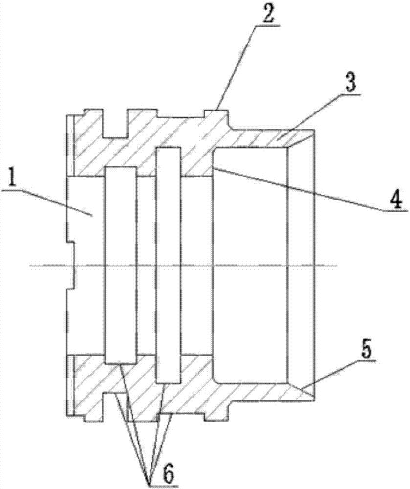
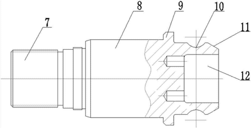
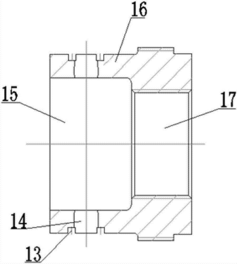
[0042] Such as Figure 1-Figure 8As shown, the mechanical locking device of the hydraulic cylinder includes an auxiliary piston 2, an auxiliary rod 8 and a nut holder 16; an installation through hole 1 is arranged inside the auxiliary piston 2, and one end of the auxiliary piston 2 extends outward to form a coaxial connection with the installation through hole 1. The retaining ring 3, the diameter of the inner ring of the retaining ring 3 is larger than the diameter of the installation through hole 1, a positioning step 4 is formed between the bottom of the inner ring of the retaining ring 3 and the installation through hole 1, and the opening end of the inner ring of the retaining ring 3 is inclined to form an inner cone surface 5. One end of the auxiliary rod 8 protrudes to...


PUM


Abstract

The invention relates to a hydraulic cylinder mechanical locking device which comprises a secondary piston, a secondary rod and a nut holding frame. The secondary rod is mounted in a mounting through hole of the secondary piston, a positioning ring of the secondary rod and a positioning step of the secondary piston are mutually matched and positioned, one end of the nut holding frame with a counter bore can axially translate along the secondary rod and is inserted into or drawn out of a cavity between a baffle ring of the secondary piston and the outside of the secondary rod, and a steel ball in the nut holding frame can be clamped into or drawn out of an annular groove of the secondary rod in the translation process of the nut holding frame. The invention further discloses a mechanically-locked hydraulic cylinder base don the hydraulic cylinder mechanical locking device and a locking method of the hydraulic cylinder. According to the locking device, the steel ball cannot contact with the hydraulic cylinder, the hydraulic cylinder cannot be damaged, unlocking pressure ranges from 0.5MPa to 1MPa and is low and uniform, synchronism in the unlocking process is good, force bearing points are positioned on the steel ball and the nut holding frame, locking force is large, impact loads can be born, the locking device is high in positioning accuracy, service life is prolonged, and the locking effect of the hydraulic cylinder is improved.

Description

technical field [0001] The invention relates to a hydraulic cylinder assembly, which belongs to the field of hydraulic machinery equipment. More specifically, the invention relates to a mechanical locking device for a hydraulic cylinder. Based on the mechanical locking device for a hydraulic cylinder, the invention also discloses a mechanical locking device. Hydraulic cylinder and its locking method. Background technique [0002] As the executive element in the hydraulic system, the hydraulic cylinder has the characteristics of smooth movement, low noise and large load, and is widely used. The action of the oil cylinder is controlled by the hydraulic valve. In general engineering hydraulic systems, the hydraulic cylinder stays at any position or at a fixed point and bears a certain load force, which is realized by a hydraulic locking circuit. But the internal leakage of the hydraulic valve is inevitable. In some special fields (such as aviation and military), it is necess...

Claims


Application Information

Patent Timeline
Patent Type & Authority Applications(China)
IPC IPC(8): F15B15/26
CPCF15B15/261F15B2015/268
Inventor 毛銡
Owner LUZHOU CHANGXIN HYDRAULIC MACHINERY MFG CO LTD
Why Eureka
Try Eureka