Planetary gear transmission

A planetary gear, planetary gear shaft technology, applied in gear transmission, gear lubrication/cooling, belt/chain/gear, etc., can solve the problems of high transmission manufacturing and installation costs, increased transmission axial size and weight, etc.

Active Publication Date: 2017-10-27
NANJING HIGH SPEED GEAR MFG
View PDF5 Cites 14 Cited by
  • Summary
  • Abstract
  • Description
  • Claims
  • Application Information

AI Technical Summary

Problems solved by technology

[0005] Therefore, the technical problem to be solved by the present invention is that the separate radial sliding bearing and axial sliding bearing in the planetary gear transmission

Method used


Image

  • Planetary gear transmission
  • Planetary gear transmission
  • Planetary gear transmission

Examples


Embodiment 1

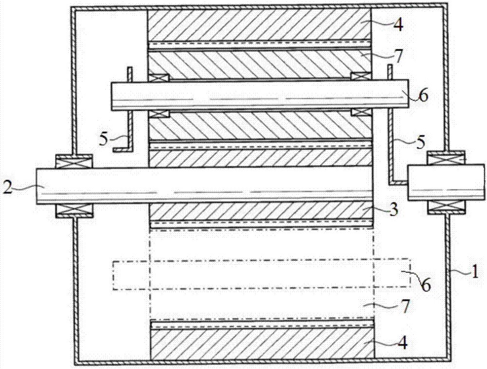
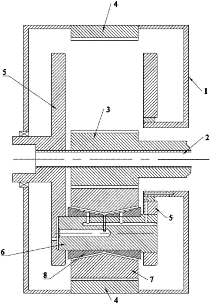
[0093] This embodiment provides a planetary gear transmission, such as image 3 shown, including

[0094] box 1,

[0095] The inner ring gear 4 is fixed on the inner wall of the box body 1;

[0096] The transmission shaft 2 is coaxial with the ring gear 4 and rotatably arranged on the case body 1 as a power output end;

[0097] The sun gear 3 is fixed on the transmission shaft 2;

[0098] The planet carrier 5 is rotatably arranged on the box body 1 as a power input end;

[0099] There is at least one planetary gear shaft 6, the axis of which is fixed on the planet carrier 5 parallel to the axis of the transmission shaft 2;

[0100] The planetary gear 7 is rotatably sleeved on each planetary gear shaft 6, located radially inside the ring gear 4 and radially outside the sun gear 3, and meshes with the ring gear 4 and the sun gear 3 respectively; it also includes

[0101] There are at least two sliding bearings 8, which are sleeved on the planetary gear shaft 6 in parallel i...

Embodiment 2

[0127] This embodiment provides a planetary gear transmission, which differs from the planetary gear transmission provided in Embodiment 1 only in that the axially outer wall surface of the sliding bearing 8 is fixed on the planet carrier 5, and the radially inner surface of the sliding bearing 8 is not fixed on the On the planetary gear shaft 6, it is only sleeved on the planetary gear shaft 6. In the planetary gear transmission with this structure, the axial load and radial load applied to the sliding bearing 8 by the planetary gear 7 are directly transmitted to the planetary carrier 5 without being transmitted to the planetary carrier 5 through the planetary gear shaft 6, so that the planetary gear shaft 6 bears the axial and radial loads of part of the planetary gear 7, and protects the planetary gear 6.

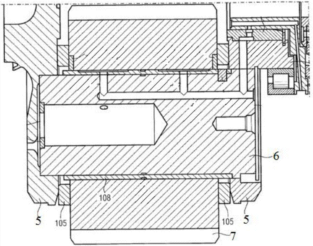
[0128] As a preferred embodiment, such as Figure 6 As shown, among the two sliding bearings 8 that are sleeved side by side on the planetary gear shaft 6 in the axial ...

Embodiment 3

[0132] This embodiment provides a planetary gear transmission, such as Figure 7 and Figure 8 As shown, the difference from the planetary gear transmissions provided in Embodiment 1 and Embodiment 2 is that: among the two sliding bearings 8 that are sleeved in parallel on the planetary gear shaft 6 in the axial direction, the first radial direction of one sliding bearing 8 The axial outer wall surface of the extension part 81 is fixed on the planet carrier 5 ; the first axial positioning part 82 of the other sliding bearing 8 is fixed on the planet gear shaft 6 .

[0133] In the planetary gear transmission with this structure, the axial load and radial load of the planetary gear 7 can be directly transmitted to the planet carrier 5 through the sliding bearing 8, and can be transmitted to the planetary gear shaft 6 through the sliding bearing 8, and then transmitted to the planetary gear shaft. on the stand. That is to say, the planetary gear transmission provided in this em...


PUM

PropertyMeasurementUnit
Angleaaaaaaaaaa

Abstract

The invention discloses a planetary gear transmission which comprises a box, a planetary gear, a sun gear, an inner gear ring, a planetary gear shaft, a transmission shaft and at least two sliding bearings which are arranged on the planetary gear shaft in parallel in a sleeving mode in the axial direction and located between the planetary gear shaft and the planetary gear. The two sliding bearings are matched to form a sunken part; the sun gear is fixed to the transmission shaft, the sliding bearings are fixed to the planetary gear shaft or a planetary support or the planetary gear, and the sunken part limits axial motion of the planetary gear or a radial protruding portion of the planetary gear limits axial motion of the sunken part, so that the axial motion of the planetary gear is limited inside the sunken part or the radial protruding portion of the planetary gear shaft, and an axial load and a radial load of the planetary gear act on the inner wall face of the sunken part or the radial protruding portion of the planetary gear shaft; accordingly, the sliding bearings bear the axial load and the radial load of the planetary gear at the same time, the axial size and the weight of the transmission can be decreased, and the manufacturing and installing cost of the transmission is lowered.

Description

technical field [0001] The invention relates to a transmission in the wind power industry, in particular to a planetary gear transmission. Background technique [0002] The planetary gear transmission used in wind power equipment in the prior art is a speed-increasing device, and its structure is mostly like the planetary gear transmission disclosed in Chinese patent document CN202182159U, such as figure 1 As shown, it includes a case body 1, an inner ring gear 4 fixed on the case body 1, a planetary carrier 5 and a transmission shaft 2 rotatably connected to the case body 1, and several planetary gear shafts fixed on the planetary carrier 5 6. The axis of the planetary gear shaft 6 is parallel to the axis of the transmission shaft 2. The planetary gear sleeved on the planetary gear shaft 6, the sun gear 3 fixed on the transmission shaft 2, and the planetary gear 5 are located between the ring gear 4 and the sun gear. Between 3, the planetary gear 5 meshes with the ring gea...

Claims


Application Information

Patent Timeline
IPC IPC(8): F16H3/44F16H57/04F16H57/08F16C33/10
Inventor 杨玉磊何爱民路会龙张合超戚松
Owner NANJING HIGH SPEED GEAR MFG
Why Eureka
Try Eureka