Supercharge Your Innovation With Domain-Expert AI Agents!

Ultralow input power supply circuit for passive sensing network and power supply method realized by adopting circuit

A technology of input power and sensing network, which is applied in the direction of output power conversion device, DC power input conversion to DC power output, electrical components, etc., and can solve the problem of lack of energy supply for passive sensing nodes

Inactive Publication Date: 2017-10-27
HARBIN INST OF TECH
View PDF6 Cites 2 Cited by
  • Summary
  • Abstract
  • Description
  • Claims
  • Application Information

AI Technical Summary

Problems solved by technology

[0005] The present invention is to solve the energy supply problem of the existing lack of passive sensing nodes in the case of ultra-low input power

Method used


Image

  • Ultralow input power supply circuit for passive sensing network and power supply method realized by adopting circuit
  • Ultralow input power supply circuit for passive sensing network and power supply method realized by adopting circuit
  • Ultralow input power supply circuit for passive sensing network and power supply method realized by adopting circuit

Examples


specific Embodiment approach 1

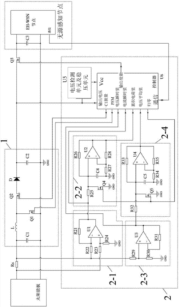
[0048] Specific embodiment one, combine 1 to Figure 4 Describe this embodiment, the ultra-low input power energy supply circuit for passive sensory network described in this embodiment, it includes solar panel, current sampling resistor Rs and PMOS tube Q3, it is characterized in that it also includes boost circuit (1) and maximum power point tracking control circuit (2),

[0049] The boost circuit (1) includes an inductor L, an electrolytic capacitor C1, an electrolytic capacitor C2, an NMOS transistor Q1, a PMOS transistor Q2 and a diode D,

[0050] The maximum power point tracking control circuit (2) includes a current amplification circuit (2-1), a current integration circuit (2-2), a voltage sampling circuit (2-3), a voltage integration circuit (2-4), a voltage detection unit and voltage stabilizing unit and controller,

[0051] The positive pole of the solar panel is simultaneously connected to one end of the current sampling resistor Rs and the non-inverting input en...

specific Embodiment approach 2

[0065]Embodiment 2. This embodiment is a further description of the ultra-low input power energy supply circuit for passive sensory networks described in Embodiment 1. The current amplification circuit (2-1), the current integration circuit (2- 2), the voltage sampling circuit (2-3) and the voltage integration circuit (2-4) are all implemented by operational amplifiers.

specific Embodiment approach 3

[0066] Specific embodiment three. This embodiment is a further description of the ultra-low input power energy supply circuit for passive sensing network described in specific embodiment one. The current amplifying circuit (2-1) is used to amplify the current on the resistor Rs Current, the output value of the instantaneous current signal output terminal of the current amplification circuit (2-1) is the instantaneous value of the current,

[0067] The current integration circuit (2-2) contains NMOS transistor Q4 inside, and the output value of the cumulative current signal output terminal of the current integration circuit (2-2) is the integral of the current in a period of time. According to Q=∫I(t)dt, a period of time The integral of the internal current is the input charge, which can be returned to zero through the NMOS transistor Q4,

[0068] The output value of the instantaneous voltage signal output terminal of the voltage sampling circuit (2-3) is the instantaneous valu...


PUM


Abstract

The invention relates to an ultralow input power supply circuit for a passive sensing network and a power supply method realized by adopting the circuit and relates to the field of power supply of passive sensing nodes. The invention aims at solving the problem of power supply of an existing circuit under the condition of ultralow input power when the passive sensing nodes are lacked. For reducing sampling power consumption, the application adopts the following steps: calculating a mean value of voltage and current by using an integrating circuit, carrying out resistive subdivision on terminal voltage of a capacitor C1 as input voltage and then transmitting the voltage into a voltage follower consisting of an operational amplifier U3; subsequently, transmitting the voltage into the integrating circuit consisting of an operational amplifier U4, wherein an output value of the operational amplifier U4 is a mean value of the voltage in a period of time; only reading output values of the operational amplifiers U2 and U4 at a set interval, calculating out the mean value of the voltage and the current in the time range, and further calculating out input power by a controller, thereby reducing energy consumption of frequent sampling. The ultralow input power supply circuit is used for supplying power for the passive sensing nodes.

Description

technical field [0001] The invention relates to an ultra-low input power energy supply circuit for a passive sensory network and an energy supply method realized by using the circuit. Background technique [0002] Passive sensing networks (Energy-harvesting WSNs, EH-WSNs) usually use solar cells (PVCell) to obtain solar energy in the environment, but there are two problems in directly connecting solar cells to passive sensing nodes. First, the output power of the solar cell is as figure 2 As shown in the middle curve 1, the power has a concave function relationship with the output voltage, so the output current needs to be controlled to maximize the output power. This method is called the maximum power point tracking (MPPT) control method. Second, a large-capacity capacitor is usually used to store energy in a passive sensing node, and its charging speed depends on the voltage difference between the output voltage of the solar cell and the energy storage capacitor. Therefor...

Claims


Application Information

Patent Timeline
IPC IPC(8): H02M3/158G05F1/67
CPCG05F1/67H02M3/158
Inventor 张扬高宏程思瑶李建中
Owner HARBIN INST OF TECH
Features
  • R&D
  • Intellectual Property
  • Life Sciences
  • Materials
  • Tech Scout
  • Unparalleled Data Quality
  • Higher Quality Content
  • 60% Fewer Hallucinations
Learn More