Flat cable type coil cloth leftover detection device

A detection device and coil technology, applied in the direction of processing textile material equipment configuration, etc., can solve the problems of long detection distance, easy interference of detection results, unstable detection system, etc., to achieve the effect of improving the detection rate

Inactive Publication Date: 2017-10-31
NANJING UNIV OF SCI & TECH
View PDF5 Cites 1 Cited by
  • Summary
  • Abstract
  • Description
  • Claims
  • Application Information

AI Technical Summary

Problems solved by technology

[0002] In the traditional dyeing process, the cloth dyeing workers observe the operation of the cloth and the degree of dyeing at the entrance and exit of the dyeing machine. The dyeing time of the cloth in the dyeing machine is determined by the experience of the workers, which results in uneven dyeing of the cloth. poor quality cloth
[0003] Chinese patent 201320589221.8 discloses a cloth head detector and a dyeing machine using it. M...

Method used


Image

  • Flat cable type coil cloth leftover detection device
  • Flat cable type coil cloth leftover detection device
  • Flat cable type coil cloth leftover detection device

Examples


Embodiment Construction

[0018] The present invention will be described in further detail below in conjunction with the accompanying drawings.

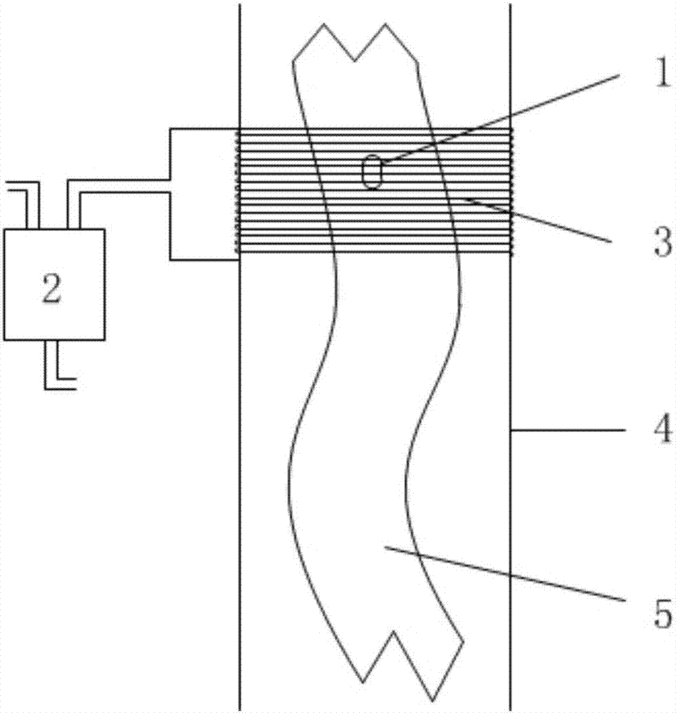
[0019] The traditional cloth head detection device has a small built-in induction coil, and the strength of the detection signal is determined by the distance between the magnetic bead and the coil. The farther the distance is, the weaker the signal is, which makes the detection unstable and prone to missed detection. The invention changes the structure of the conventional cloth head detector and uses a brand-new design scheme of the induction coil. The test shows that the detection rate of the cloth head can almost reach 100%, and the detection accuracy is very high.

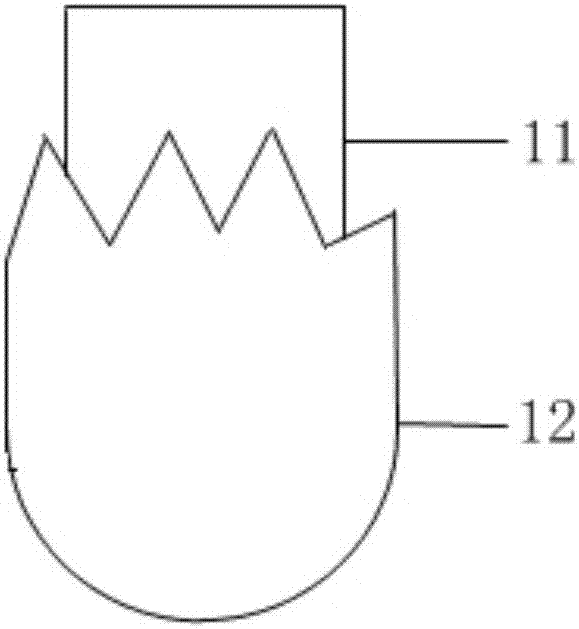
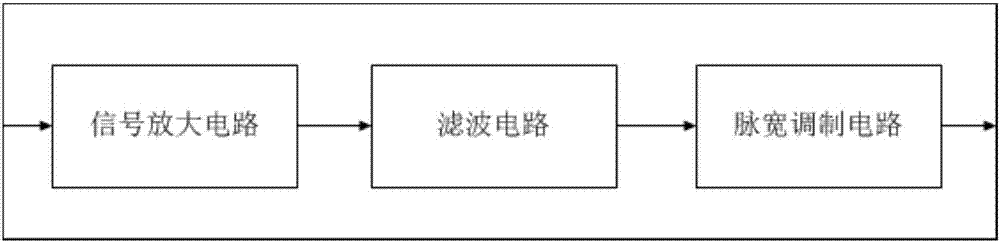
[0020] combine Figure 1 to Figure 5 , a line-type coil cloth head detection device, including a magnetic bead 1, a detection circuit 2 and an induction coil 3, the magnetic bead 1 is fixed on the cloth to be dyed, and circulates in the cloth dyeing machine together with the cloth to be dyed....


PUM


Abstract

The invention discloses a flat cable type coil cloth leftover detection device. The flat cable type coil cloth leftover detection device comprises a magnetic ball, a detection circuit and an induction coil, wherein the magnetic ball is fixed on to-be-dyed cloth, the induction coil is arranged on the outer wall of a cloth guiding pipe of a cloth dyeing machine and is connected with the detection circuit; and when the magnetic ball moves in the cloth guiding pipe of the cloth dyeing machine and passes through the induction coil, the detection circuit detects a signal, processes the signal and output the counting signal of a fixed phase width. According to the flat cable type coil cloth leftover detection device, the motion parameters of cloth in a dyeing cylinder can be simply, rapidly, accurately and efficiently measured, so that the detection rate of cloth leftover is greatly increased.

Description

technical field [0001] The invention belongs to the field of automatic control of textile printing and dyeing, and in particular relates to a wire arrangement type coil cloth head detection device. Background technique [0002] In the traditional dyeing process, the cloth dyeing workers observe the operation of the cloth and the degree of dyeing at the entrance and exit of the dyeing machine. The dyeing time of the cloth in the dyeing machine is determined by the experience of the workers, which results in uneven dyeing of the cloth. The cloth is of poor quality. [0003] Chinese patent 201320589221.8 discloses a cloth head detector and a dyeing machine using it. Most cloth head detectors on the market use this structure, and its detection accuracy is determined by the distance between the magnetic beads and the detector. The farther the distance is, the farther the accuracy will be. When the magnetic beads swing together with the cloth in the cloth guide tube, the detectio...

Claims


Application Information

Patent Timeline
IPC IPC(8): D06B23/20
CPCD06B23/20
Inventor 朱明敏胡茂海
Owner NANJING UNIV OF SCI & TECH
Why Eureka
Try Eureka