Automatic production device for precise machining of rotating pin holes of ratchet wrench heads

An automatic production, wrench head technology, applied in metal processing equipment, drilling/drilling equipment, metal processing and other directions, can solve the problems of flying knife, large drilling position error, reduce production efficiency, etc., to reduce manual operation, The effect of realizing the processing position and ensuring the processing accuracy

Pending Publication Date: 2017-11-03
湖南精专自动化技术有限公司
View PDF0 Cites 10 Cited by
  • Summary
  • Abstract
  • Description
  • Claims
  • Application Information

AI Technical Summary

Problems solved by technology

Due to the small size of the ratchet wrench head parts, it is very difficult to process the repin hole 903. The traditional method generally adopts ordinary clamps to clamp the ratchet wrench head tightly, and then drills holes through ordinary lathes, milling machines or manually. Sometimes workers are required to hold the ratchet wrench head one by one on the lathe and then take it to the milling machine for milling, or take it to ma

Method used


Image

  • Automatic production device for precise machining of rotating pin holes of ratchet wrench heads
  • Automatic production device for precise machining of rotating pin holes of ratchet wrench heads
  • Automatic production device for precise machining of rotating pin holes of ratchet wrench heads

Examples


Embodiment Construction

[0026] In order to enable those skilled in the art to better understand the technical solution of the present invention, the present invention will be described in detail below in conjunction with the accompanying drawings. The description in this part is only exemplary and explanatory, and should not have any limiting effect on the protection scope of the present invention. .

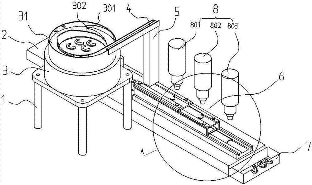
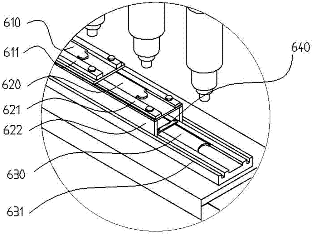
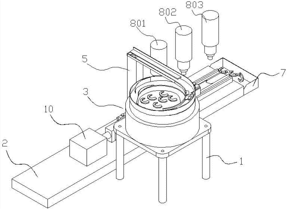
[0027] Such as Figure 1-Figure 7 Shown, the concrete structure of the present invention is: a kind of finishing automatic production equipment that is used for ratchet wrench head repinning hole, it comprises the vibrating feeding tray 3 that is arranged on the frame 1 and the drilling machine device 8; Said vibrating feeding tray 3 is provided with a spiral surrounding feeding plate 31; the spiral surrounding feeding plate 31 is provided with a limited layer guide plate 301, a discharge trough 303, and a material selection trough 304 in sequence along the moving direction of the parts; The baffle pl...


PUM

PropertyMeasurementUnit
Heightaaaaaaaaaa

Abstract

The invention discloses an automatic production device for precise machining of rotating pin holes of ratchet wrench heads. The automatic production device comprises a vibration feeding disc and a drilling machine device; a spiral surrounding type feeding plate is arranged in the vibration feeding disc; a layer-limited guide plate, a material discharging groove and a material sorting groove are sequentially arranged on the spiral surrounding type feeding plate in the moving direction of parts; a matching baffle is arranged opposite to the layer-limited guide plate, and the spiral surrounding type feeding plate is connected to a discharging rail; the discharging rail is connected to a guide bin; a pushing device is arranged at the lower end of the guide bin and comprises an upper-layer feeding sliding groove and a lower-layer feeding sliding groove which are stacked mutually; a first pushing plate is arranged on the upper-layer feeding sliding groove; a second pushing plate is arranged on the lower-layer feeding sliding groove; the tail end of the first pushing plate and the tail end of the second pushing plate are connected to a telescopic device; and the drilling machine device is positioned right above the pushing device. According to the automatic production device, orientation sorting can be carried out rapidly on the ratchet wrench heads in batches, drilling and reaming machining can be carried out on the ratchet wrench heads, the production efficiency is high, machining is stable and reliable, the precision is high, the potential safety hazard is avoided, and the production efficiency is improved.

Description

technical field [0001] The invention belongs to the field of hardware tool manufacturing, and in particular relates to an automatic production equipment for finishing the repin hole of a ratchet wrench head. Background technique [0002] Ratchet wrench head structure as Figure 7 As shown, the overall shape is arc shape, one end is thin, one end is wide, and the wide end is provided with a pin hole 903; the inner cutting edge 901 is a polygonal structure, and the outer arc surface 902 is arc. Due to the small size of the ratchet wrench head parts, it is very difficult to process the repin hole 903. The traditional method generally adopts ordinary clamps to clamp the ratchet wrench head tightly, and then drills holes through ordinary lathes, milling machines or manually. Sometimes workers are required to hold the ratchet wrench head one by one on the lathe and then take it to the milling machine for milling, or take it to manual drilling. Every ratchet wrench head to be proce...

Claims


Application Information

Patent Timeline
IPC IPC(8): B23B41/00B23Q7/00
CPCB23B41/00B23Q7/00Y02P70/10
Inventor 王再德王胜得王恒王琼
Owner 湖南精专自动化技术有限公司
Why Eureka
Try Eureka