Plate chamfering machine

A technology for chamfering machines and plates, which is applied to machine tools, grinders, metal processing equipment and other directions suitable for grinding the edge of workpieces. Effect

Pending Publication Date: 2017-11-03
深圳市乐维机械有限公司
View PDF5 Cites 8 Cited by
  • Summary
  • Abstract
  • Description
  • Claims
  • Application Information

AI Technical Summary

Problems solved by technology

[0002] The board cutting method is generally to cut the large raw material size into the required small size in the form of whole stack sawing. Since the four corners of the board are very sharp after sawing and cutting, it is not only easy to cause harm to people but also affects the post-production process. The service life of equipment rollers, pressure wheels, conveyor belts and tooling fixtures, so they need to be rounded or right-angled

Method used


Image

  • Plate chamfering machine
  • Plate chamfering machine
  • Plate chamfering machine

Examples


Embodiment Construction

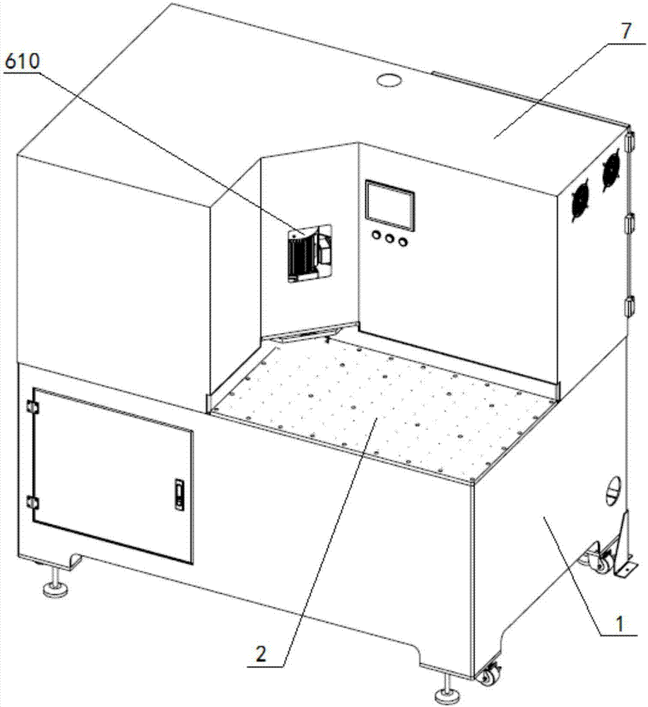
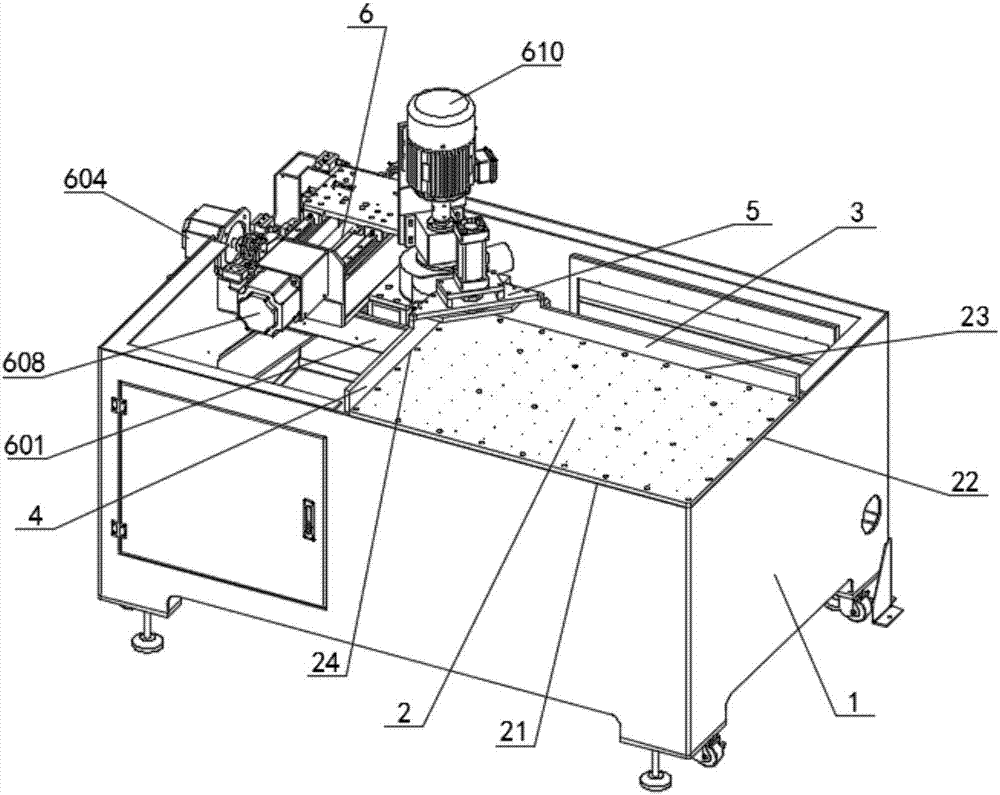
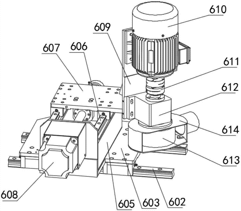
[0026] In order to make the objectives, technical solutions and advantages of the present invention clearer, the following further describes the present invention in detail with reference to the accompanying drawings and embodiments. It should be understood that the specific embodiments described here are only used to explain the present invention, but not used to limit the present invention. The front and back of the embodiments described in the embodiments are subject to the accompanying drawings, which are only used to clarify the positional relationship and are not used to limit the .

[0027] On the contrary, the present invention covers any alternatives, modifications, equivalent methods and schemes defined by the claims in the spirit and scope of the present invention. Further, in order to enable the public to have a better understanding of the present invention, in the following detailed description of the present invention, some specific details are described in detail. ...


PUM


Abstract

The invention discloses a plate chamfering machine. The plate chamfering machine comprises a rack for providing a supporting base, a gas-floating platform used for placing a plate, an X-axis fixed backup side, a Y-axis fixed backup side, a beam pressing assembly used for pressing the plate, a machine head used for cutting the plate, and a machine enclosure which covers the rack, wherein the gas-floating platform is fixedly arranged on one side corner at the top end of the rack; the X-axis fixed backup side, the Y-axis fixed backup side and the beam pressing assembly are arranged on the gas-floating platform; and the machine head is arranged on a position, which is not provided with the gas-floating platform, of the rack. The plate chamfering machine has the beneficial effects that: the X-axis fixed backup side and the Y-axis fixed backup side are arranged, so that the plate can be quickly positioned, processing efficiency is high, a thin plate also can be processed, the chamfering effect is better than that of a forming knife, and the chamfering size can be freely switched by parameters; and the processed plate is free of burrs and can reduce harm on people, and the service life of a roller wheel, the service life of a pressure wheel and the service life of a conveyor belt of back-end processing equipment are not affected.

Description

Technical field [0001] The invention specifically relates to a plate chamfering machine. Background technique [0002] The cutting method of the board is generally to cut the large raw material size into the required small piece size in the form of stack sawing. Since the four corners of the board are very sharp after sawing the material, it not only causes harm to people but also affects the subsequent process. The service life of equipment rollers, pressing wheels, conveyor belts, and tooling fixtures must be rounded or right-angled. Summary of the invention [0003] In order to effectively solve the above problems, the present invention provides a plate chamfering machine. [0004] The technical scheme of the present invention is as follows: [0005] A plate chamfering machine, including: [0006] 1. A frame that provides a supporting foundation; [0007] An air-floating platform for placing plates; [0008] One X axis is fixed to the side; [0009] One Y axis is fixed to the side; ...

Claims


Application Information

Patent Timeline
IPC IPC(8): B24B9/18B24B55/06
CPCB24B9/18B24B55/06
Inventor 李德浩宋永其赵小明
Owner 深圳市乐维机械有限公司
Why Eureka
Try Eureka