
Movable cutting rack used for single-flow cutting equipment

A technology of cutting equipment and cutting frame, which is applied in the field of machinery manufacturing and casting, can solve the problems of inconvenient storage and transportation, easy to overturn, single function, etc., and achieve the effect of simple structure, convenient installation and heavy load

Pending Publication Date: 2017-11-03
HANDAN HENGGONG METALLURGICAL MACHINERY CO LTD
View PDF0 Cites 0 Cited by
  • Summary
  • Abstract
  • Description
  • Claims
  • Application Information

AI Technical Summary

Problems solved by technology

[0002] For the production of large-scale cast iron profiles, the traditional cutting frame is generally fixed. The cutting frame on the market generally has a single function, large size, and inconvenient storage and transportation. Although some have retractable workpiece support seats, they lack The support for the workpiece support seat will easily cause the frame to be unstable and easy to fall over when processing long workpieces; and the plate may move during the operation, resulting in errors in the cutting length

Method used


Image

  • Movable cutting rack used for single-flow cutting equipment
  • Movable cutting rack used for single-flow cutting equipment

Examples


Embodiment Construction

[0016] The present invention will be further described below in conjunction with accompanying drawing:

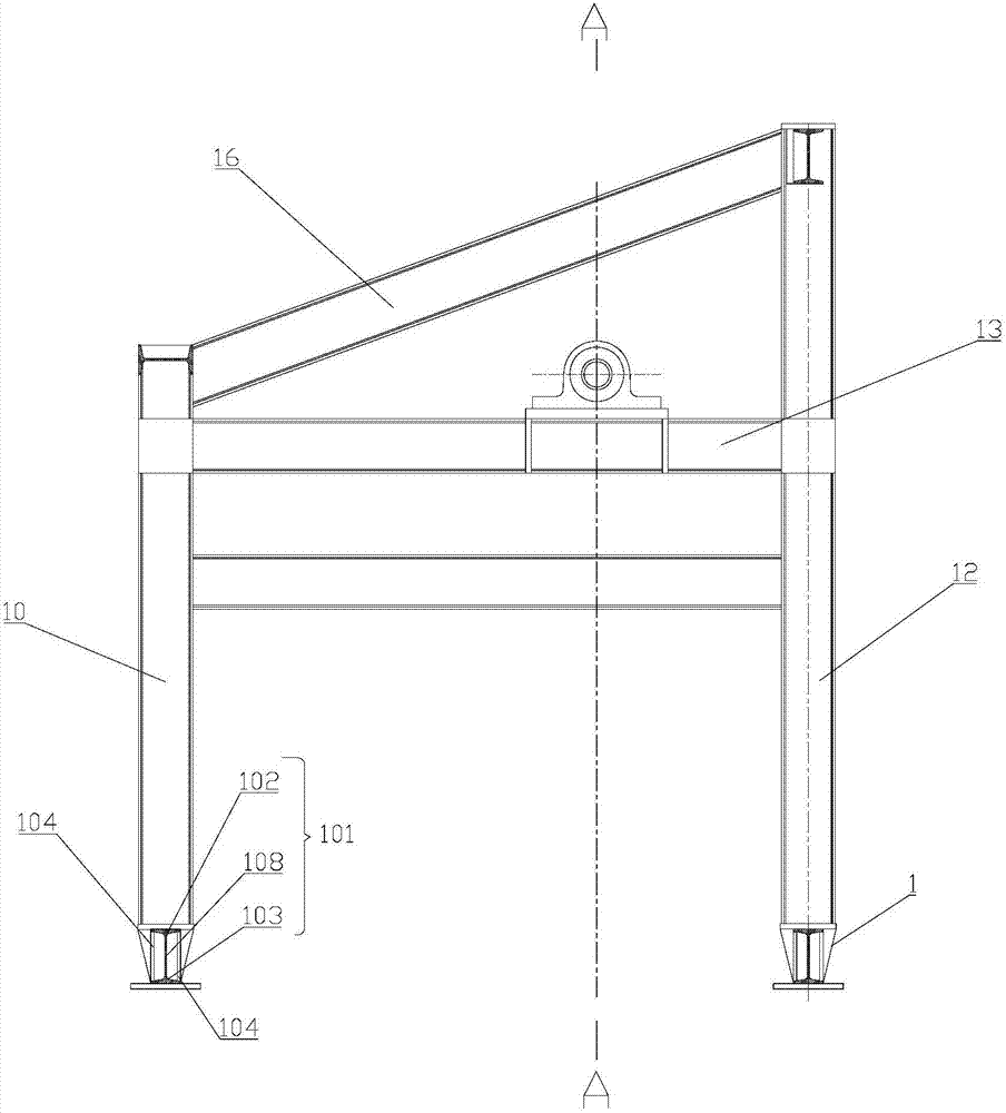
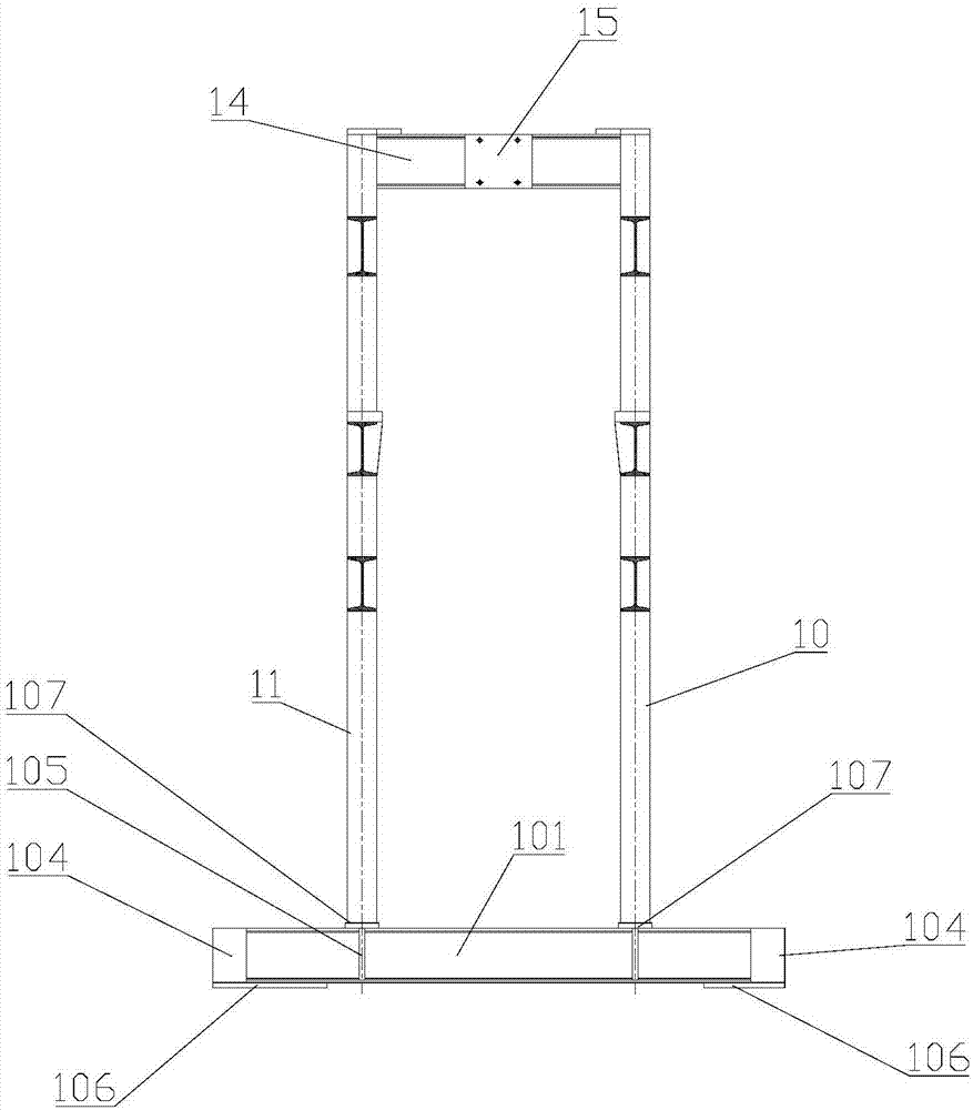
[0017] Such as Figure 1 to Figure 2 As shown, a movable cutting frame for single-flow cutting equipment provided by the present invention includes two oppositely arranged traveling wheel beams 1; the first left column 10 and the The second left column 11; the first right column 12 and the second right column arranged on another road wheel beam 1; the front beam 13 connected between the first left column 10 and the first right column 12 and the back beam connected between the second left column 11 and the second right column; the height of the first right column 12 and the second right column is greater than that of the first left column 10 and the second left column 11 Height; the top of the first right column 12 and the second right column is provided with a top connecting beam 14; the inner side of the top connecting beam 14 is provided with a cylinder block connecting ...


PUM


Abstract

The invention discloses a movable cutting rack used for single-flow cutting equipment. The movable cutting rack comprises two traveling wheel beams arranged oppositely, a first left vertical column, a second left vertical column, a first right vertical column, a second right vertical column, a front beam and a rear beam, wherein the first left vertical column and the second left vertical column are arranged on one of the traveling wheel beams, the first right vertical column and the second right vertical column are arranged on the other traveling wheel beam, the front beam is connected between the first left vertical column and the first right vertical column, and the rear beam is connected between the second left vertical column and the second right vertical column. The heights of the first right vertical column and the second right vertical column are larger than the heights of the first left vertical column and the second left vertical column. A top end connecting beam is arranged at the top ends of the first right vertical column and the second right vertical column. An oil cylinder seat connecting plate is arranged on the inner side of the top end connecting beam. A front inclining beam is arranged between the top end connecting beam and the first left vertical column. A rear inclining beam is arranged between the top end connecting beam and the second left vertical column. The rack is simple in structure, large in bearing weight and convenient to mount.

Description

technical field [0001] The invention belongs to the technical field of mechanical manufacturing and casting, and in particular relates to a movable cutting frame used on single-flow cutting equipment. Background technique [0002] For the production of large-scale cast iron profiles, traditional cutting frames are generally fixed. The cutting frames on the market generally have single functions, large volume, and inconvenient storage and transportation. Although some have retractable workpiece support seats, they lack The support for the workpiece support seat will easily cause the frame to be unstable and easy to fall over when processing a long workpiece; and the plate may move during the operation, resulting in an error in the cutting length. Contents of the invention [0003] Aiming at the problems existing in the prior art, the present invention proposes a movable cutting frame for single-stream cutting equipment. [0004] In order to achieve the above-mentioned tech...

Claims


Application Information

Patent Timeline
IPC IPC(8): B25H1/06B25H5/00B23Q1/72
CPCB23Q1/72B25H1/06B25H5/00
Inventor 魏志勇魏本立付永晟
Owner HANDAN HENGGONG METALLURGICAL MACHINERY CO LTD
Learn More