a transmission device

A transmission device and air valve technology, applied in the direction of conveyors, transportation and packaging, non-mechanical conveyors, etc., can solve the problems of high cost, poor flexibility, large installation space, etc., and achieve easy maintenance and replacement, and simple assembly , The effect of simple and fast wiring

Active Publication Date: 2019-04-12
沈路平
View PDF4 Cites 0 Cited by
  • Summary
  • Abstract
  • Description
  • Claims
  • Application Information

AI Technical Summary

Problems solved by technology

This makes the entire conveyor system require a large installation space and high cost
In addition, the existing transmission system is based on the direction of the transmission medium, the transmission path and direction are limited by the settings of the transmission medium, and cannot be automatically adjusted during the transmission process, resulting in poor flexibility
It has gradually been unable to adapt to the current needs of multi-variety, multi-task and multi-process automated production lines

Method used


Image

  • a transmission device
  • a transmission device
  • a transmission device

Examples


Embodiment Construction

[0029] The present invention will be described in further detail below in conjunction with the accompanying drawings.

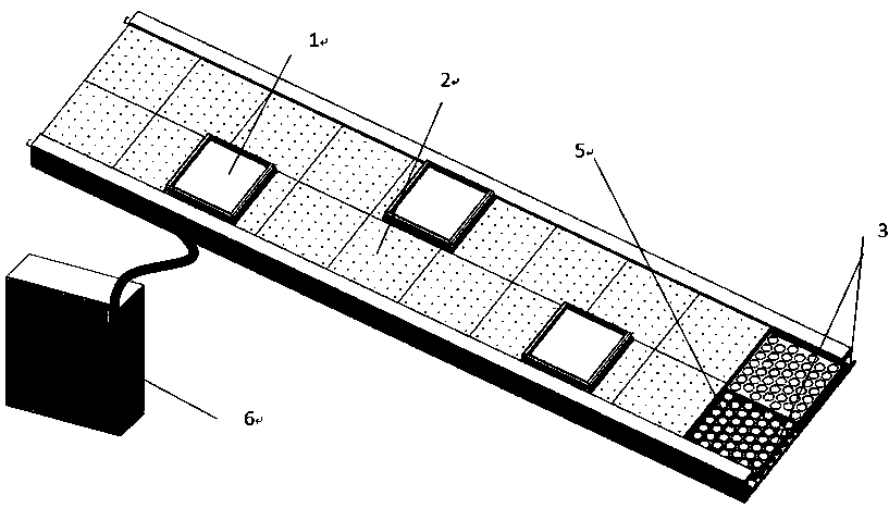
[0030] Such as figure 1 , a transmission device of the present invention, comprising a loading platform 1 , an air suspension platform 2 and a controller 6 . The object-carrying platform 1 is arranged above the air-suspension platform 2 , its upper surface is used to carry objects to be transported, and its bottom is provided with magnetic components. The air-suspension platform 2 includes an air valve module and an electromagnetic module 5, an air outlet 4 is arranged on its top, an air inlet 3 is arranged on its side, and the surface on which the loading platform 1 is carried is a plane. The air valve module is arranged in the air suspension platform 2 . The electromagnetic module of the air suspension platform is connected to the controller, and the electromagnetic module generates a moving induction magnetic field under the control of the controller. Th...


PUM


Abstract

The invention discloses a conveying device, and belongs to the field of automatic warehousing technologies and automatic production lines. The conveying device comprises an object carrying platform, an air-suspending platform and a controller; a magnetic component is arranged at the bottom of the object carrying platform; the air-suspending platform comprises an air valve module and an electromagnetic module which are arranged in the air-suspending platform; an air outlet is formed in the top of the air-suspending platform; an air inlet is formed in the side edge of the air-suspending platform; the controller is connected with the electromagnetic module; and under the electrification condition, the air valve module acts in a magnetic field generated by the electromagnetic module, and an airflow passage is formed among the air inlet, the air valve module and the air outlet, so as to generate air buoyancy to support the object carrying platform. The conveying device adopts modular design and is simple in wiring, precise positioning control and fixed position locking of the object carrying platform are realized, and conveying in any position can be realized.

Description

technical field [0001] The invention relates to the field of automatic storage technology and automatic production line, in particular to a multi-channel high-precision automatic equipment supply and transmission device. Background technique [0002] The existing conveying system is widely used in highly automated production lines such as logistics sorting, mobile phone assembly, semiconductor chip packaging, and assembly lines. The existing transmission system mainly uses sprockets, chains, belts, etc. as the transmission medium, and the transmission is realized by controlling the transmission speed and direction through the motor and the transmission mechanism, and the transmission is stopped at a specific position by using the stopper and the lifting device. This makes the entire conveyor system require a large installation space and high costs. In addition, the existing transmission system is based on the direction of the transmission medium, and the transmission path a...

Claims


Application Information

Patent Timeline
Patent Type & Authority Patents(China)
IPC IPC(8): B65G54/02
CPCB65G54/02
Inventor 沈路平刘锡宏陈伟刚
Owner 沈路平
Why Eureka
Try Eureka