Detection method and detection device of brightness response error rate of medical display device

A display device and brightness response technology, applied in optics, nonlinear optics, static indicators, etc., can solve problems such as brightness errors of medical images, inability to correctly diagnose diseases, and differences in brightness of medical images

Inactive Publication Date: 2017-11-03
HISENSE VISUAL TECH CO LTD
View PDF4 Cites 7 Cited by
  • Summary
  • Abstract
  • Description
  • Claims
  • Application Information

AI Technical Summary

Problems solved by technology

However, since there may be some differences in the LCD screens used by different medical display devices, for the same medical image data, there may be differences in the brightness of medical images displayed on different medical display devices
At the same time, for a fixed medical display device, in the long-term use proce

Method used


Image

  • Detection method and detection device of brightness response error rate of medical display device
  • Detection method and detection device of brightness response error rate of medical display device
  • Detection method and detection device of brightness response error rate of medical display device

Examples


Embodiment 1

[0066] Such as Figure 5 As shown, the embodiment of the present invention provides a method for detecting the luminance response error rate of a medical display device. The execution subject of each step of the method may be a detection device, and the detection device may be a CPU (Central Processing Unit, central processing unit) At least one of processing modules (hardware) such as SOC (System on a Chip, system-on-a-chip or system-on-chip), FPGA (Field Programmable Gate Array, field programmable gate array), and of course at least one of the above-mentioned processing modules can also be included electronic equipment, such as PC (personal computer, personal computer) and so on. For another example, the detection device may also be software for implementing the following steps, which is not limited here.

[0067] The detection method includes the following steps:

[0068] Step S101, output the P value sequence to the medical display device, so as to obtain the measurement...

Embodiment 2

[0125] In the first embodiment, the detailed process of the method for detecting the luminance response error rate performed by the detection device has been given. Wherein, the detection device can be a separate processing module (CPU, SOC, etc.), and can also include multiple processing modules. Considering that a single processing module is performing the entire detection process, the load of the processing module will be relatively heavy. Therefore, In this embodiment, the upper computer and the lower computer cooperate to implement the detection method of the luminance response error rate, so as to reduce the load on the upper computer.

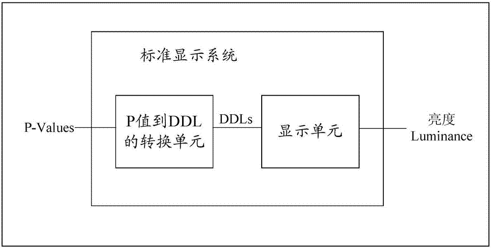
[0126] The upper computer can control the operation of the lower computer, and the lower computer is directly connected with the medical display device to input control signals to the medical display device. It is worth noting that the medical display device here only contains figure 1 The two-unit device shown may not be a packaged dev...

Embodiment 3

[0172] This embodiment also provides a detection device for the luminance response error rate of a medical display device. For the description of the detection device, reference may be made to the first embodiment, so as to implement the method described in the first embodiment.

[0173] Such as Figure 9 As shown, the detection device may include:

[0174] Output module 21, is used for inputting P value sequence to medical display device;

[0175] The receiving module 22 is configured to acquire a measurement sequence corresponding to the P value sequence, the P value sequence includes M P values, the measurement sequence includes M brightness measurement values ​​corresponding to the M P values, and the M A brightness measurement value includes a first brightness measurement value and a second brightness measurement value, M≥3;

[0176] A processing module 23, configured to respectively calculate a first JND value and a second JND value corresponding to the first brightnes...


PUM


Abstract

The invention discloses a detection method and a detection device of the brightness response error rate of a medical display device, and relates to the technical field of error detection. The objective of the invention is to achieve detection of the brightness response error rates of medical display devices. The method comprises steps of outputting a P value sequence to a medical display device so as to acquire a measurement sequence corresponding to the P value sequence; calculating a JND value sequence corresponding to the P value sequence; calculating a brightness standard value corresponding to each JND value on a GSDF curve so as to obtain a standard sequence consisting of M brightness standard values; and according to a standard sequence and the measurement sequence, calculating the error rate sequence.

Description

technical field [0001] The invention relates to the technical field of error detection, in particular to a detection method and a detection device for a brightness response error rate of a medical display device. Background technique [0002] With the development of computer science, medical image informatics has become a rapidly developing field in the world. The use of DICOM (Digital Imaging and Communications in Medicine, medical digital imaging and communication) as a medical image data standard enables medical image data to be transmitted, exchanged and stored between different medical display devices produced by different manufacturers. [0003] Usually, medical display devices display gray-scale images, and diseases are diagnosed according to the brightness of the gray-scale images. However, since there may be some differences in the liquid crystal screens used by different medical display devices, for the same medical image data, the brightness of medical images dis...

Claims


Application Information

Patent Timeline
IPC IPC(8): G09G3/00G02F1/13G01M11/02G09G5/10
CPCG01M11/02G02F1/1309G09G3/006G09G5/10
Inventor 田广郭攀
Owner HISENSE VISUAL TECH CO LTD
Why Eureka
Try Eureka