Electric wire and electric cable auger machine

A technology of electric wire and cable and auger, which is applied in the field of cable production equipment, can solve the problems of difficulty in adjusting the number of twisted wires, fewer twisted layers, and uneven twisting, so as to simplify the production process, expand the number of twisted layers, Effect of improving stranding quality

Active Publication Date: 2017-11-03
安徽腾飞特种电缆科技有限公司
View PDF12 Cites 2 Cited by
  • Summary
  • Abstract
  • Description
  • Claims
  • Application Information

AI Technical Summary

Problems solved by technology

However, there are several problems in the current twisting machine: (1) only one-way twisting can be done when twisting, and two-way twisting is seldom performed. It is easy to cause single-strand winding and affect the stranding quality; (2) the current auger machine has a small number of stranding layers, and the number of stranding wires is difficult to adjust, which greatly limits the application range of the product; (3) the current auger machine The machine cannot perform the wrapping process synchronously, and needs to be processed step by step; (4) The current winch machine is complicated to operate in the cable forming step, the meter counting operation is extensive and inaccurate, and it is inconvenient to move after cable forming

Method used


Image

  • Electric wire and electric cable auger machine
  • Electric wire and electric cable auger machine
  • Electric wire and electric cable auger machine

Examples


Embodiment Construction

[0033] In order to explain in detail the technical content, structural features, achieved goals and effects of the technical solution, the following will be described in detail in conjunction with specific embodiments and accompanying drawings.

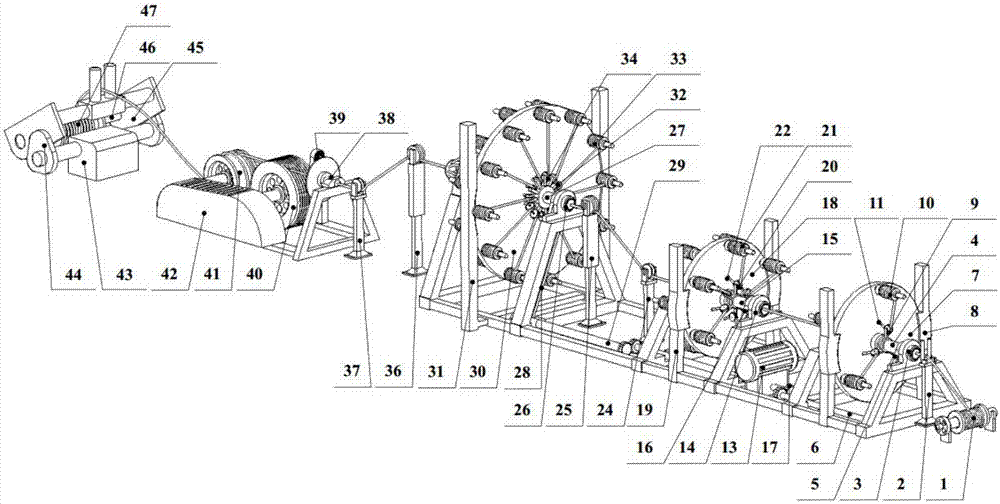
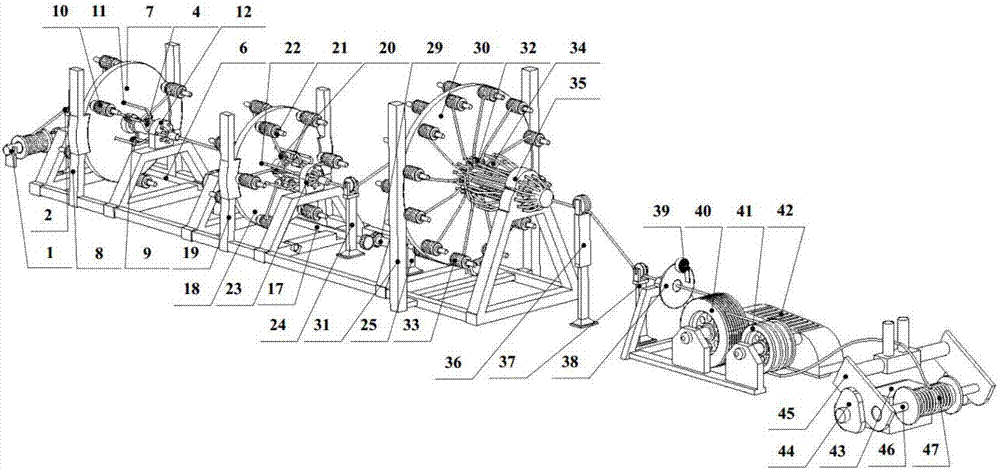
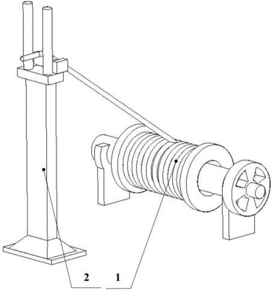
[0034] see Figure 1-13, a wire and cable wringer of this embodiment is characterized in that it includes a main line shaft 1, a positioning frame 2, a first-level wire sleeve 3, a first-level rotary sleeve 4, a first-level transmission chain 5, and a first-level transmission shaft 6 , first-level turntable 7, first-level turntable frame 8, first-level directional wheel 9, first-level splitting shaft 10, first-level disc hole 11, first-level cluster die head 12, rotating motor 13, second-level wire inlet sleeve 14, two-level Secondary rotary sleeve 15, secondary transmission chain 16, secondary transmission shaft 17, secondary turntable 18, secondary turntable frame 19, secondary directional wheel 20, secondary branch line shaft 21, s...


PUM


Abstract

The present invention belongs to the field of electric cable production equipment, and more particularly relates to an electric wire and electric cable auger machine which comprises a main wire rotating shaft, a positioning frame, wire inlet sleeves at all levels, rotation sleeves at all levels, transmission chains at all levels, transmission shafts at all levels, rotating disks at all levels, rotating disk racks at all levels, directional wheels at all levels, branching wire rotating shafts at all levels, disk holes at all levels, cluster die heads at all levels, a rotating electric motor, a pull-up group of low wheels, a pull-up group of high wheels, a pull-down group of high wheels, a pull-down group of low wheels, package rotating sleeves, non-woven cloth rods, a metering rotary wheel, a tightening rotary wheel, a synchronous steering electric motor, a rotary shaft platform, a support rack platform rod, a wire take-up rod, a sleeve rod and a wire forming rotary shaft. The beneficial effects of the electric wire and electric cable auger machine are that (1) bidirectional twisting can be realized, and branching wire interweaving and non-uniform intertwisting can be prevented; (2) the number of twisting layers can be enlarged and the number of stranded wires can be adjusted; (3) lapping operation can be performed at the same time; (4) accurate metering can be realized, cabled wires can be bundled tight, and convenience of blanking cabled wires can be improved.

Description

technical field [0001] The present invention relates to a wringer, more specifically to a wire and cable wringer, which belongs to the field of cable production equipment. Background technique [0002] With the improvement of my country's economic level, the total production and demand of wire and cable in my country are also rising sharply. Although the wire and cable industry is only a supporting industry, it accounts for 1 / 4 of the output value of China's electrical industry. It has a wide range of products and a wide range of applications. Its products are mainly used in the transmission of strong electric energy in the transmission, distribution, transmission, transformation, and power supply lines. The passing current is large (tens of amps to thousands of amps), and the voltage is high (220V to 35KV and above). Therefore, in the production process of the auger, it is necessary to go through the steps of twisting, insulation extrusion (wrapping), and cabling. Howeve...

Claims


Application Information

Patent Timeline
IPC IPC(8): H01B13/02
CPCH01B13/02H01B13/0207H01B13/0235H01B13/0271Y02W30/82
Inventor 卢飞
Owner 安徽腾飞特种电缆科技有限公司
Why Eureka
Try Eureka