
Livestock feed drying and collecting device

A collection device and drying technology, which is applied in the direction of drying gas arrangement, feed, drying solid materials, etc., can solve the problems of dust removal and sterilization treatment, increased processing cost, easy to be affected by moisture and agglomeration, etc., and achieve good drying collection effect and simple structure , strong practical effect

Inactive Publication Date: 2017-11-07
ZHENGZHOU LIFUAI BIOLOGICAL TECH CO LTD
View PDF6 Cites 19 Cited by
  • Summary
  • Abstract
  • Description
  • Claims
  • Application Information

AI Technical Summary

Problems solved by technology

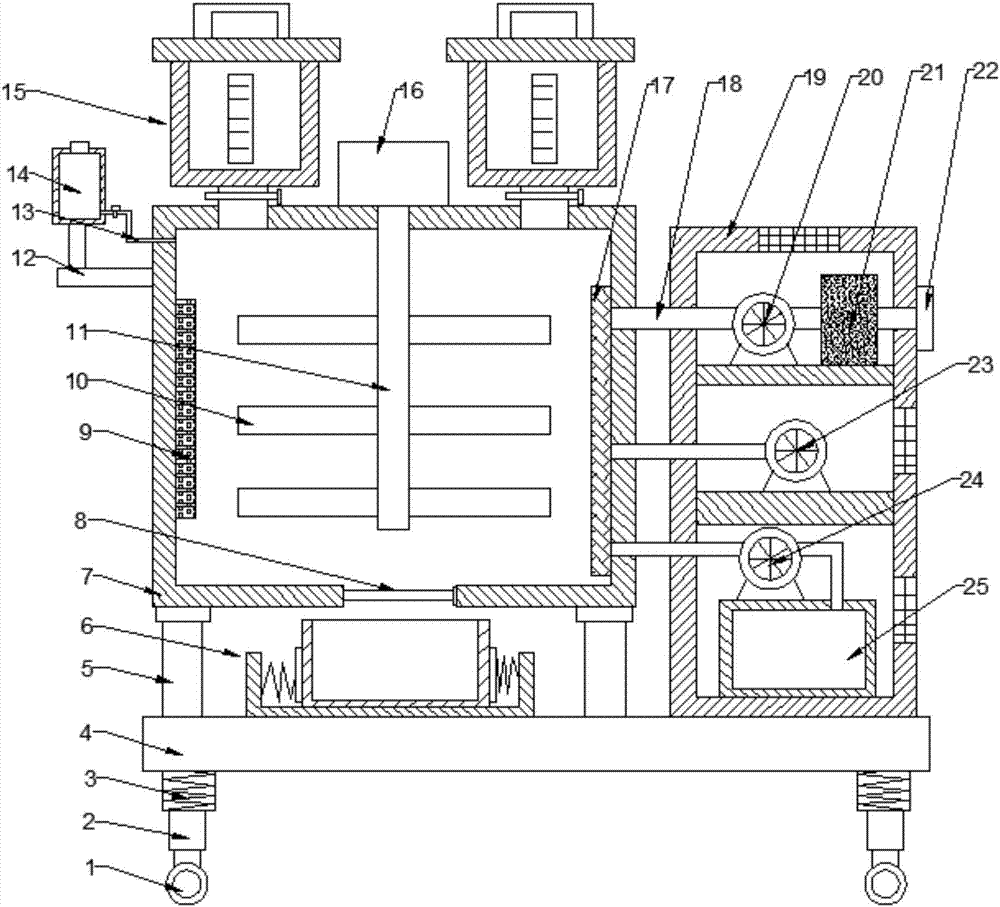
[0002] Nowadays, with the development of society and economic growth, the development of agriculture is also getting faster and faster. In the production and planting of agricultural products, mixing equipment is often used; the indispensable part of agriculture is feed, which is often placed in a place that is prone to moisture and condensation. Therefore, it is necessary to use feed mixing equipment; the feed mixer is mainly used to stir various feeds, the purpose is to dehumidify the feed, which is beneficial to improve the digestibility and better absorb the nutrients of the feed; on the other hand, it is necessary for transportation, storage, mixing and Granulation is more convenient, and the efficiency and quality are better; the existing feed mixing device has a single function, the processing cost is increased, and the drying efficiency is low, and the existing feed mixer still cannot perform dust removal and sterilization for the feed; therefore, it needs to be improved , now provides a livestock feed drying collection device

Method used


Image

  • Livestock feed drying and collecting device
  • Livestock feed drying and collecting device
  • Livestock feed drying and collecting device

Examples


Embodiment Construction

[0015] The technical solution of this patent will be further described in detail below in conjunction with specific embodiments.

[0016] Embodiments of the present patent are described in detail below, examples of which are shown in the drawings, wherein the same or similar reference numerals designate the same or similar elements or elements having the same or similar functions throughout. The embodiments described below by referring to the figures are exemplary, and are only used to explain the patent, and should not be construed as limiting the patent.

[0017] In the description of this patent, it is to be understood that the terms "center", "upper", "lower", "front", "rear", "left", "right", "vertical", "horizontal", The orientation or positional relationship indicated by "top", "bottom", "inner", "outer", etc. is based on the orientation or positional relationship shown in the drawings, and is only for the convenience of describing this patent and simplifying the descri...


PUM


Abstract

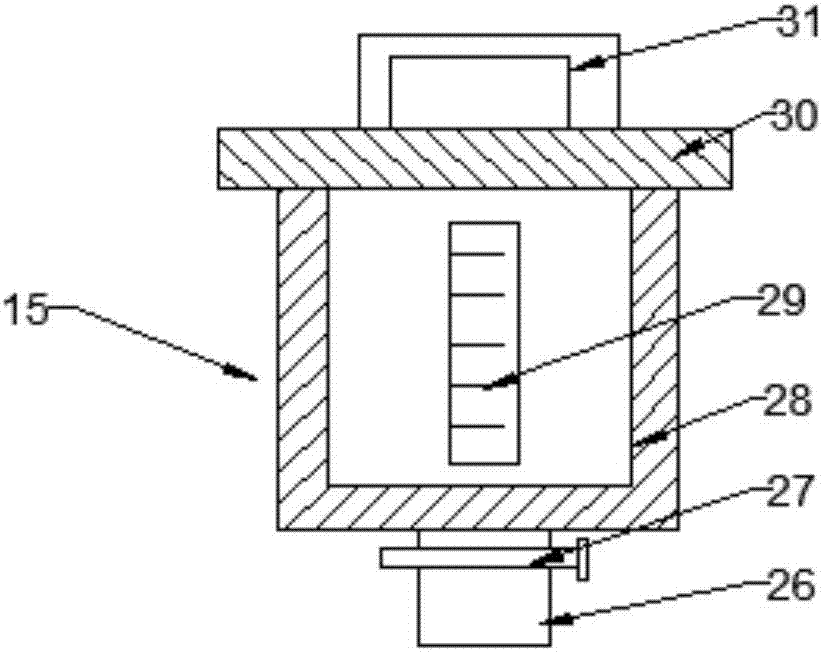
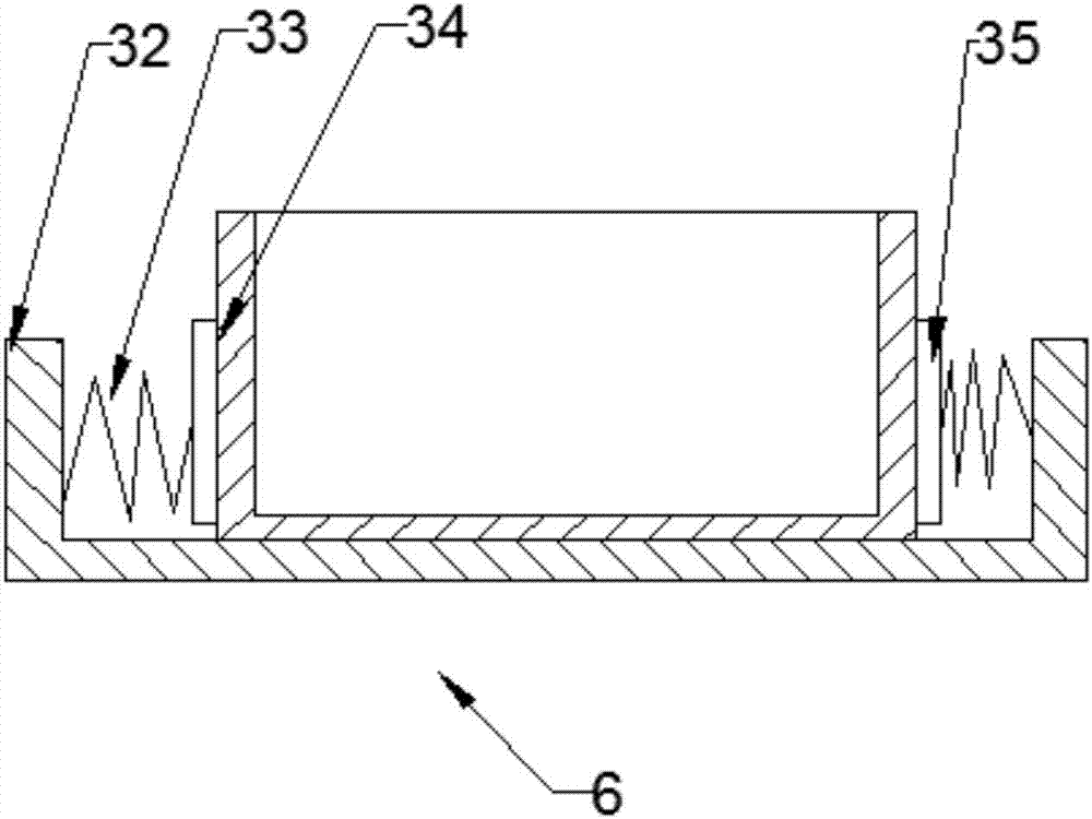
The invention provides a livestock feed drying and collecting device and belongs to the technical field of livestock feed processing. Feeding devices are arranged on the two sides of the upper portion of a box body. The lower end of the right side of a liquid storage box is connected with the box body through a liquid outflow pipe. Stirring pieces are fixedly arranged on a rotary shaft in a welded mode. An electric telescopic plate is arranged at the bottom of the box body. The right end of a moisture exhaust fan is connected with a drying filter through a connecting pipe. A hot air blower is arranged in the middle of an inner cavity of a device box. The upper portion of a dust collecting box is connected with a suction ventilator through a connecting pipe, and the left end of the suction ventilator is connected with the box body through a connecting pipe. According to the device, the left end of the moisture exhaust fan is connected with the box body through the connecting pipe, so that the function of exhausting moisture in the box body is achieved; the left end of the hot air blower is connected with the box body through the connecting pipe, so that the function of drying feed in the box body is achieved; the device has the advantages of being simple in structure, high in practicality and good in drying and collecting effect.

Description

technical field [0001] The invention relates to a facility related to livestock feed processing, in particular to a livestock feed drying and collecting device. Background technique [0002] Nowadays, with the development of society and economic growth, the development of agriculture is also getting faster and faster. In the production and planting of agricultural products, mixing equipment is often used; the indispensable part of agriculture is feed, which is often placed in a place that is prone to moisture and condensation. Therefore, it is necessary to use feed mixing equipment; the feed mixer is mainly used to stir various feeds, the purpose is to dehumidify the feed, which is beneficial to improve the digestibility and better absorb the nutrients of the feed; on the other hand, it is necessary for transportation, storage, mixing and Granulation is more convenient, and the efficiency and quality are better; the existing feed mixing device has a single function, the proc...

Claims


Application Information

Patent Timeline
IPC IPC(8): A23N17/00A23L3/28F26B21/00F26B25/00B07B4/00
CPCA23N17/007A23L3/28B07B4/00F26B21/00F26B25/00
Inventor 张健健
Owner ZHENGZHOU LIFUAI BIOLOGICAL TECH CO LTD
Learn More