Top grinding machine
A technology of top grinding machine and plug, which is applied in the direction of grinding frame, grinding machine, grinding machine parts, etc., can solve the problems of time-consuming and laborious, unable to grind buildings, reduce grinding efficiency, etc., to achieve convenient operation and improve grinding efficiency. , the effect of simple structure
- Summary
- Abstract
- Description
- Claims
- Application Information
AI Technical Summary
Problems solved by technology
Method used
Image
Examples
Embodiment 1
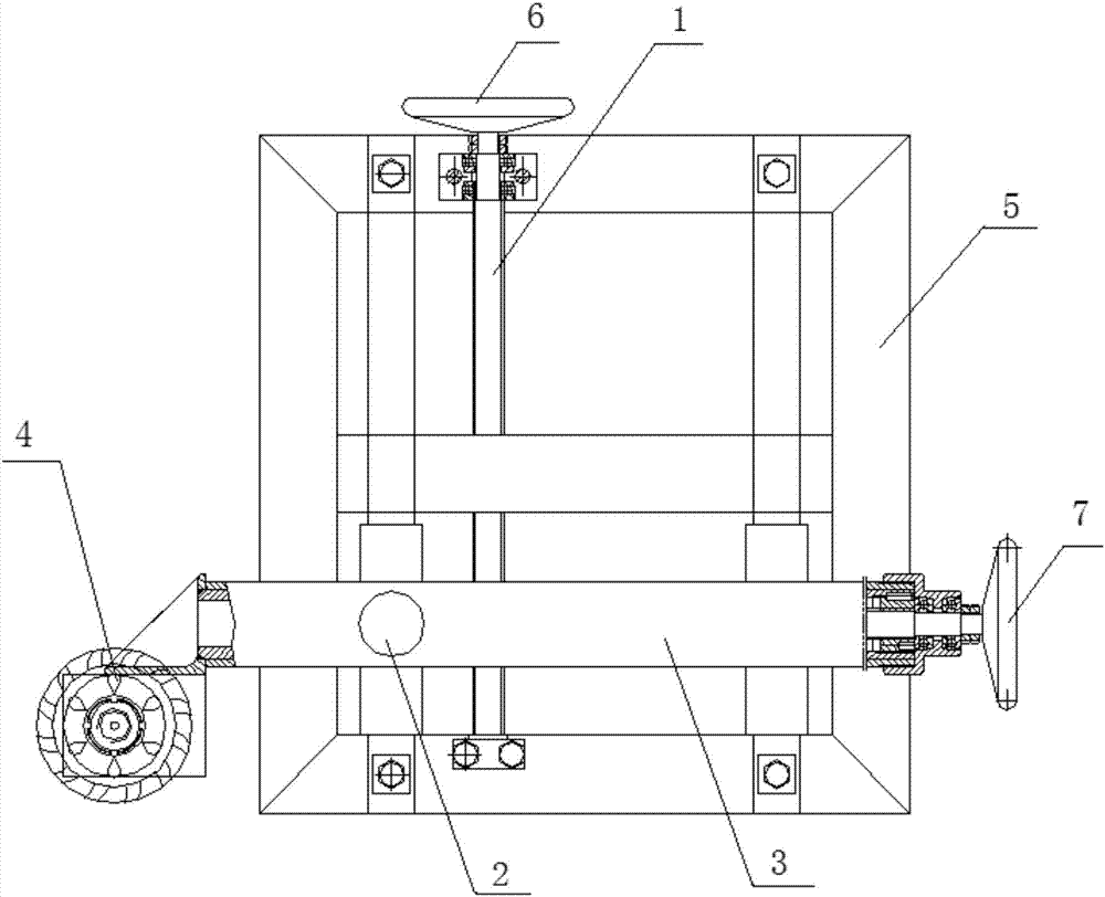
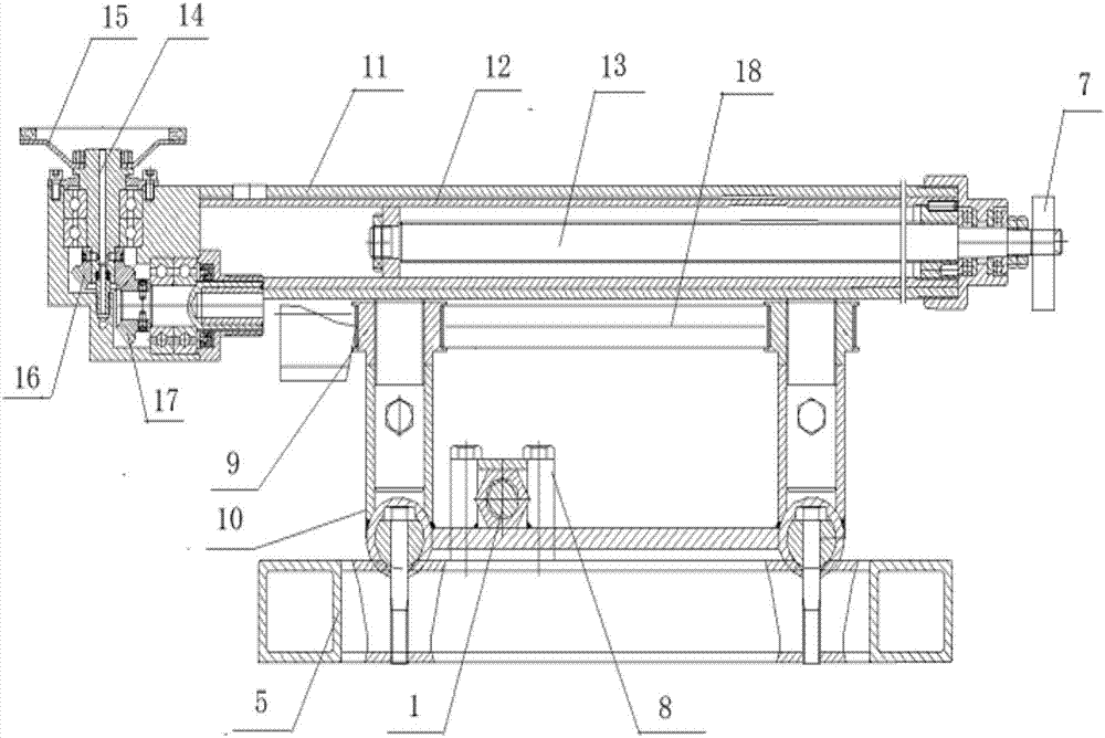
[0023] Such as Figure 1-2 As shown, a top grinding machine in this embodiment includes a frame 5, a top grinding head assembly 4, a Y-axis assembly 3 for controlling the movement of the top grinding head assembly 4 along the Y-axis direction, and a Y-axis assembly for controlling the Y-axis assembly. 3. The Z-axis assembly 2 moving along the Z-axis direction, the X-axis assembly 1 and the drive assembly for controlling the movement of the Z-axis assembly 2 along the X-axis direction; the grinding head assembly 4 and the drive assembly It is arranged on the Y-axis assembly 3; the abutment head assembly 4 and the drive assembly are connected in transmission
[0024] The X-axis assembly 1 includes an X-axis, a moving block and an X-axis runner 6. The X-axis is a screw, and the two ends of the X-axis are rotatably connected with the frame 5. The X-axis runner 6 Fixedly connected with one end of the X-axis, the center of the moving block 8 is provided with a threaded hole, the ce...
Embodiment 2
[0033] Based on Embodiment 1, the driving assembly in this embodiment includes a driving motor and a flexible shaft, the housing of the driving motor is fixed to the outer wall of the guide tube 11 for leveling, and the flexible shaft includes a drive motor with one end connected to the driving motor. The mandrel and the protection tube sleeved on the outside of the mandrel, lubricating oil is arranged between the protection tube and the mandrel; the other end of the flexible shaft is in transmission connection with the grinding head assembly 4;
[0034] Such as figure 2 As shown, the crown head assembly 4 includes a grinding disc 15, a transmission shaft 14, a first bevel gear 16 and a second bevel gear 17, one end of the transmission shaft 14 is fixedly connected to the rotation center of the grinding disc 15, and the first The conical gear 16 is coaxially connected to the transmission shaft 14 , the second conical gear 17 is coaxially connected to one end of the flexible s...
Embodiment 3
[0037] Based on Embodiment 1, the grinding disc 15 described in this embodiment is arranged parallel to the X-axis and the Y-axis and perpendicular to the Z-axis. The grinding disc 15 includes a disc body, a water nozzle and a through hole, and the disc body is a ring. The outer ring on the front of the disc body is provided with several rectangular protrusions at intervals and several of the protrusions are arranged in a spiral shape, the inner ring of the disc body is arranged lower than the outer ring of the disc body, and the through hole is arranged on the outer ring of the disc body. Between the inner ring and the outer ring of the disc body, a circular protrusion is arranged on the front of the disc body along the edge of the inner ring, and the water spout is arranged in the circular protrusion and is rotatably connected with the annular protrusion , the back of the disk body is connected to the transmission shaft by transmission, and the transmission shaft is provided ...
PUM
 Abstract
Description
Claims
Application Information
 - R&D Engineer
- R&D Manager
- IP Professional
- Industry Leading Data Capabilities
- Powerful AI technology
- Patent DNA Extraction
Browse by: Latest US Patents, China's latest patents, Technical Efficacy Thesaurus, Application Domain, Technology Topic, Popular Technical Reports.
© 2024 PatSnap. All rights reserved.Legal|Privacy policy|Modern Slavery Act Transparency Statement|Sitemap|About US| Contact US: help@patsnap.com


