
Low-power-dissipation intelligent door lock

A smart door lock, low power consumption technology, used in building locks, lock applications, electric registration locks, etc., can solve the problem of affecting the user's door lock experience, increasing the cost of sliding covers and detection devices, and high power consumption of infrared sensing devices problem, to achieve the effect of low hardware cost, long service life and good unlocking effect

Inactive Publication Date: 2017-11-07
浙江公共安全技术研究院有限公司
View PDF5 Cites 7 Cited by
  • Summary
  • Abstract
  • Description
  • Claims
  • Application Information

AI Technical Summary

Problems solved by technology

The sliding cover method is to install a mechanical sliding cover outside the door lock panel, and install a detection device inside the sliding cover. Whenever the user opens the door, sliding the sliding cover wakes up the door lock. This method increases the cost of the sliding cover and the detection device. When the user opens the door It is necessary to increase the action of sliding the sliding cover, and some noise will be generated when sliding the sliding cover, which will affect the user's experience of using the door lock; the infrared sensing method installs an infrared device on the door lock, senses the user's approach through infrared rays, and wakes up the door lock. However, the power consumption of infrared sensing devices is generally relatively high; the bluetooth sensing method is suitable for mobile phone bluetooth to open the door lock, the bluetooth module inside the door lock regularly detects the user's mobile phone through bluetooth wireless communication, and wakes up when the user's mobile phone is detected For door locks, this method is only suitable for door locks that support mobile phone Bluetooth remote door opening, and the power consumption of Bluetooth wireless communication is still much larger than that of capacitive proximity sensing.

Method used


Image

  • Low-power-dissipation intelligent door lock
  • Low-power-dissipation intelligent door lock

Examples


Embodiment Construction

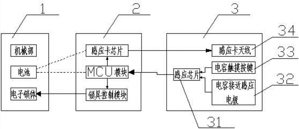
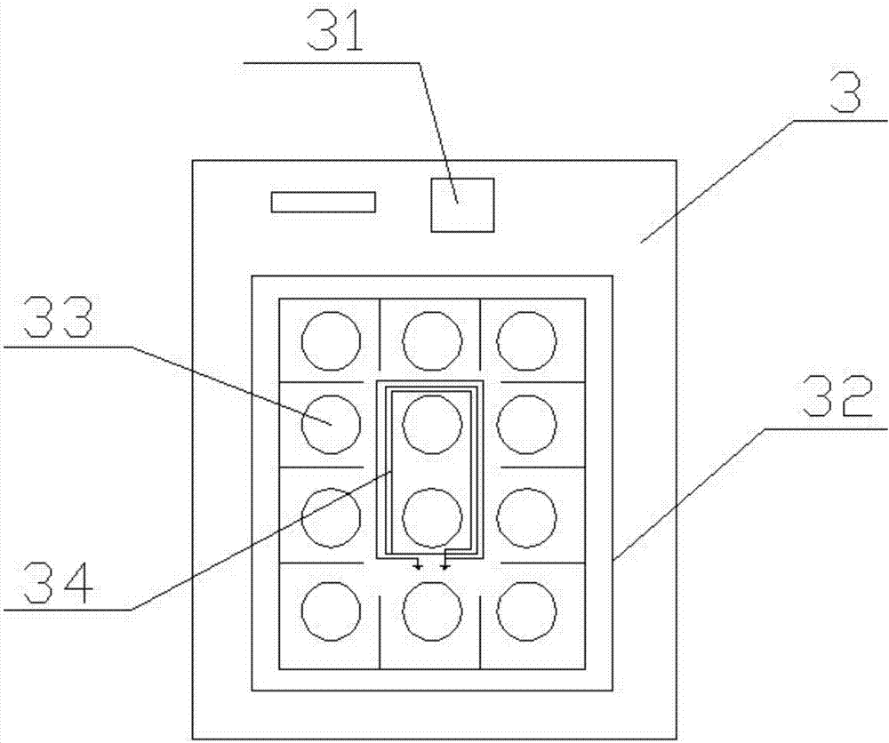
[0016] refer to figure 1 and figure 2 , a low-power intelligent door lock of the present invention, comprising an electronic lock 1, a single-chip microcomputer control module 2, a button and an antenna module 3, the electronic lock 1 is formed by mutual installation of a mechanical part, a battery and an electronic lock body, and the electronic lock 1 is connected with the single-chip microcomputer control module 2, and described single-chip microcomputer control module 2 comprises MCU module, induction card chip and lockset control module, and single-chip microcomputer control module 2 is connected with antenna module 3 with button, and described mechanical part comprises front panel, rear panel, lock Head, front handle and rear handle, the MCU module is connected with the proximity card chip and the lock control module respectively, the proximity card chip can receive the instruction signal sent by the MCU module, and the electronic lock body can receive the unlocking sign...


PUM


Abstract

The invention discloses a low-power-dissipation intelligent door lock. The low-power-dissipation intelligent door lock comprises an electronic lock, a single-chip microcomputer control module, a button and antenna module; the electronic lock is formed by installing a mechanical part, a battery and an electronic lock body, the electronic lock is connected with the single-chip microcomputer control module, and the single-chip microcomputer control module comprises an MCU module, a proximity card chip and a lock control module; and the single-chip microcomputer control module is connected with the button and antenna module. The low-power-dissipation intelligent door lock has the beneficial effects that the power dissipation of the intelligent door lock is reduced, the intelligent door lock can be dormant for a long time, the service life of the battery is long, and use and operation are convenient and quick.

Description

【Technical field】 [0001] The invention relates to the technical field of door locks, in particular to the technical field of low power consumption intelligent door locks. 【Background technique】 [0002] Compared with mechanical door locks, smart door locks have the advantages of safety and convenience, and are being more and more widely used in various occasions such as hotel rooms, company attendance, and family room doors. At present, the smart door locks on the market are usually equipped with proximity cards and touch buttons. In order for the door lock to respond quickly when the proximity card is approaching or the finger is pressed, the door lock needs to be in the work of detecting the proximity card and scanning the touch buttons all the time. In this way, the electronic door lock is in static power consumption for a long time, which makes the power consumption of the door lock larger, thus making the battery life and service life of the smart door lock short. Ther...

Claims


Application Information

Patent Timeline
IPC IPC(8): E05B49/00E05B15/00
CPCE05B49/00E05B15/00
Inventor 陶士杰吴勇杨巨星
Owner 浙江公共安全技术研究院有限公司
Learn More