Rolling bearing with self-monitoring system

A rolling bearing and self-monitoring technology, applied in the direction of bearings, bearing components, shafts and bearings, etc., can solve the problems of narrow effective frequency band, low reliability, short battery power supply time, etc., to achieve effective frequency bandwidth, high reliability, power generation With the effect of strong power supply

Active Publication Date: 2017-11-07
深圳立专技术转移中心有限公司
View PDF9 Cites 0 Cited by
  • Summary
  • Abstract
  • Description
  • Claims
  • Application Information

AI Technical Summary

Problems solved by technology

In recent years, people have proposed different forms of embedded monitoring systems one after another. Although they can solve the problem of measurement accuracy and accuracy, it is necessary to change the structure or integrity of related equipment in order to install the sensor monitoring system. Problems such as stress concentration of components cannot be realized on some equipment with complex structures or limited space; the most critical thing is that when the monitoring system needs to rotate with the inner and outer rings of the bearing, it is inconvenient to use electric wires to supply power, but to use battery power. time is short
Therefore, the existing bearing monitoring system is basically a regular and indirect non-contact measurement, and it is difficult to obtain the running status of the bearing in a timely and accurate manner.
In view of this, various forms of self-powered monitoring bearings have been proposed. The biggest problem is that the power generation performance varies greatly at different speeds, the effective frequency band is narrow, and the reliability is low.

Method used


Image

  • Rolling bearing with self-monitoring system
  • Rolling bearing with self-monitoring system
  • Rolling bearing with self-monitoring system

Examples


Embodiment Construction

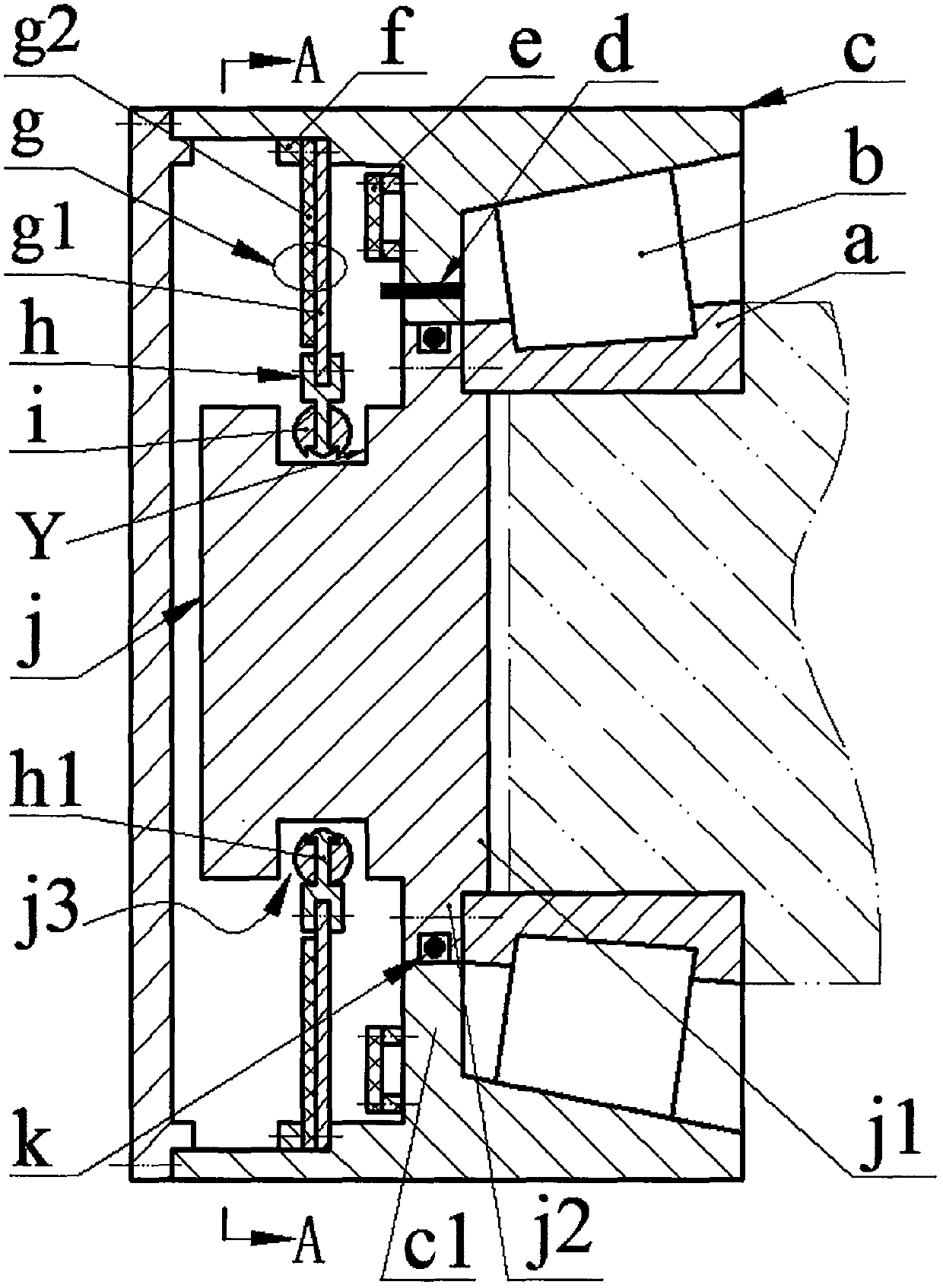
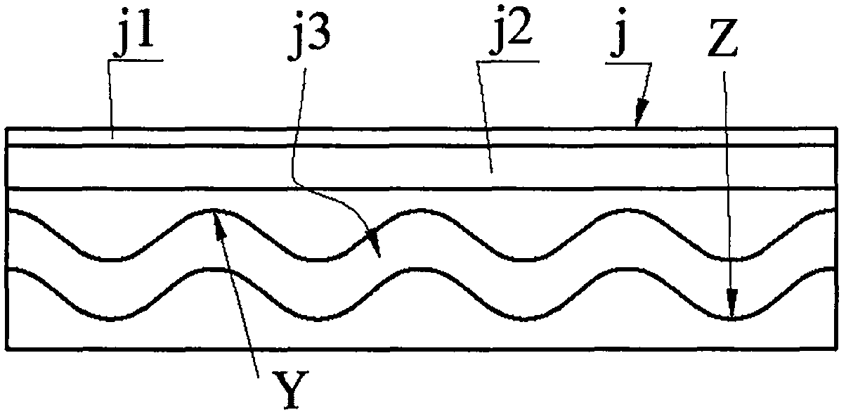
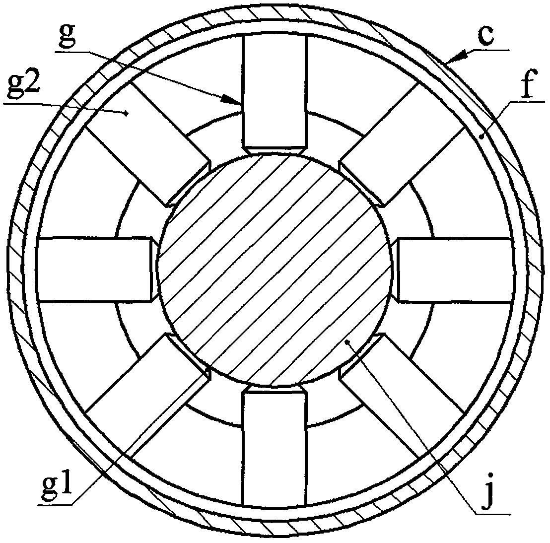
[0011] The self-monitoring tapered bearing of the present invention includes an inner ring a, a roller b, an outer ring c, a sensor d, a circuit board e, a pressure ring f, a transducer g, a camshaft j and a sealing ring k; Ring c is divided into left chamber C1 and right chamber C2, inner ring a is installed in right chamber C2 through roller b; circuit board e and sensor d are installed on annular partition c1, circuit board e is placed in left chamber C1; cam The pillow block j1 of the shaft j is set in the inner hole of the inner ring a, the shaft shoulder j2 on the camshaft j is installed on the inner ring a through screws, and the sealing ring k is crimped between the shaft shoulder j2 and the annular partition c1; A cam groove j3 is provided on the camshaft j; a transducer g is installed on the inner wall boss of the outer ring c via a screw and a pressure ring f, and the transducer g is placed in the left cavity C1, and the transducer g is composed of the base plate g1 ...


PUM


Abstract

The invention relates to a rolling bearing with a self-monitoring system, and belongs to the technical field of bearings. An outer ring is divided into left and right cavities by an annular separation plate; an inner ring is mounted in the right cavity by a roller; the annular separation plate is provided with a circuit board and a sensor; a shaft table of a cam shaft is sleeved in an inner hole of the inner ring; a shaft shoulder of the cam shaft is mounted on the inner ring; a sealing ring is pressed between the shaft shoulder and the annular separation plate; the cam shaft is provided with a cam groove; a transducer is mounted on a boss on the inner wall of the outer ring, and is formed by bonding a PZT film on a substrate; a poking block with a pin shaft is mounted at a free end of the transducer; a rolling body coats the pin shaft, and is positioned in the cam groove; when the rolling body is contacted with the peak of the cam surface on the right side of the cam groove, the transducer cannot be bent to deform; when the rolling body is contacted with the peak of the cam surface on the left side of the cam groove, the maximum stress on the PZT film is smaller than an allowed value, and the deformation on a compound layer of two laminated pieces at the free end of the transducer is smaller than an allowed value; and the transducer and the sensor are connected with the circuit board by different lead sets.

Description

technical field [0001] The invention belongs to the technical field of bearings, and in particular relates to a rolling bearing with a self-monitoring system. Background technique [0002] Bearings are indispensable basic components in the fields of machinery, vehicles, aerospace, ships and energy, and are also one of the most vulnerable parts in the transmission system. 30% of rotating machinery failures are caused by bearing failure. Therefore, bearing condition monitoring and early fault diagnosis have attracted people's attention. On-line monitoring of bearing status has gradually become an indispensable technology in the fields of large generators, ships, high-speed rail, and aircraft. The indicators to be monitored include temperature, vibration, speed, and noise. Early bearing monitoring systems were mainly plug-in. One of the disadvantages was that the distance between the sensor and the signal source was relatively long, and it was a non-contact indirect measuremen...

Claims


Application Information

Patent Timeline
Patent Type & Authority Applications(China)
IPC IPC(8): F16C41/00
CPCF16C41/00F16C2233/00
Inventor 马继杰何恒钱曾平
Owner 深圳立专技术转移中心有限公司
Why Eureka
Try Eureka