Air film type jetting device and extractor hood with same

A range hood and air film technology, which is applied in the field of air film ejection device, can solve the problems of not being able to block the escape of oil fume and cooking environment, and achieve the effect of reducing the escape of oil fume and avoiding the adhesion of oil fume

Active Publication Date: 2017-11-07
NINGBO FOTILE KITCHEN WARE CO LTD
View PDF6 Cites 3 Cited by
  • Summary
  • Abstract
  • Description
  • Claims
  • Application Information

AI Technical Summary

Problems solved by technology

However, when the above-mentioned air supply device is applied to a range hood, since the conversion ratio of dynamic pressure and static pressure is fixed, and the cooking environment used by the range hood is relatively complicated, this air supply device cannot be customized for different cooking environments. The corresponding air supply changes, so that the best effect of blocking oil fume or preventing oil fume from escaping cannot be achieved

Method used


Image

  • Air film type jetting device and extractor hood with same
  • Air film type jetting device and extractor hood with same
  • Air film type jetting device and extractor hood with same

Examples


Embodiment Construction

[0029] The present invention will be further described in detail below in conjunction with the accompanying drawings and embodiments.

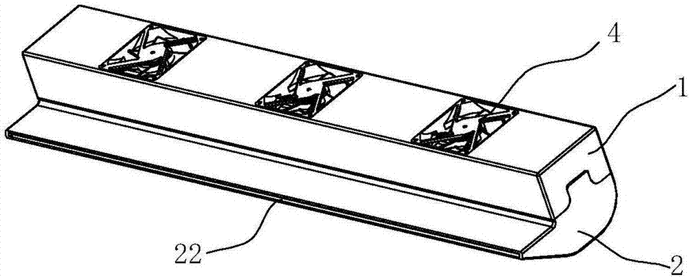
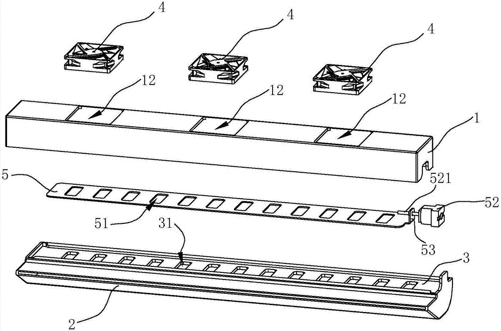
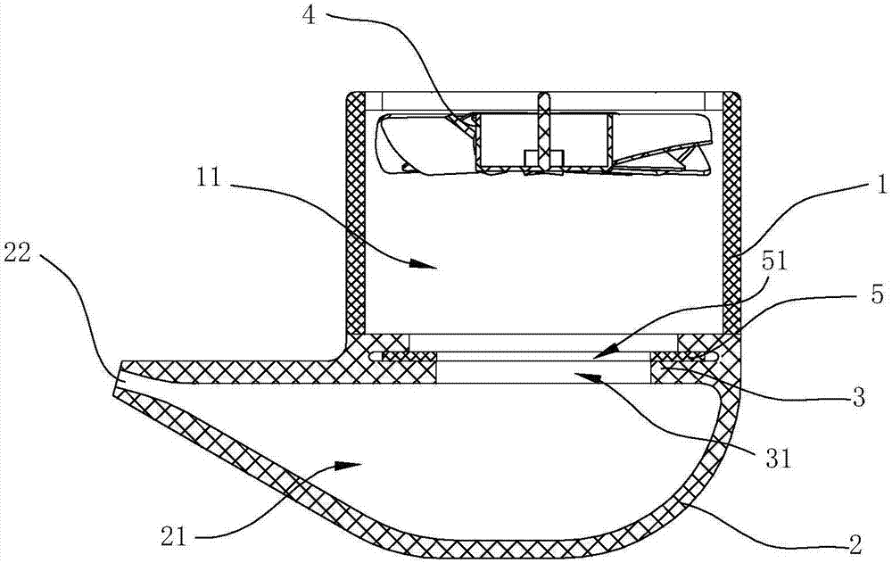
[0030] see Figure 1 to Figure 5 , a kind of air film injection device, comprises the box body that is formed with inner chamber, is provided with a cutoff plate 3 in the inner chamber, divides the inner chamber into the first chamber 11 and the second chamber 21 that communicate with each other, the first The cavity 11 communicates with the outside world, and a fan 4 is arranged therein for sucking the air from the outside into the device, and the second cavity 21 ejects air flow outward. Thus, the first cavity 11 constitutes a dynamic pressure chamber, while the second cavity 21 constitutes a static pressure chamber.

[0031] The partition plate 3 is provided with at least two first ventilation holes 31 arranged side by side and spaced apart in the length direction of the plate, so that the gas sucked into the first cavity 11 by the fan 4 p...


PUM


Abstract

The invention discloses an air film type jetting device. The air film type jetting device comprises a box body with an inner cavity. The inner cavity is internally provided with a flow separation plate so that the inner cavity can be divided into a first cavity body and a second cavity body which communicate with each other. The inner cavity body is internally provided with a draught fan which sucks in external gas. The flow separation plate is provided with at least two first vent holes which are formed at intervals. The second cavity body is provided with a nozzle from which gas is jetted out. The air film type jetting device is characterized in that one face of the flow separation plate is provided with a pressure adjusting plate which can adjust the ventilation area of the first vent holes. The invention further discloses an extractor hood with the air film type jetting device. The flow separation plate of the jetting device is additionally provided with the pressure adjusting plate, the effective ventilation area of the flow separation plate is adjusted through moving of the pressure adjusting plate, and the conversion ratio of the dynamic pressure to the static pressure is changed so that needs of different use environment can be met.

Description

technical field [0001] The invention relates to an air supply device, in particular to an air film ejection device, and a range hood using the ejection device. Background technique [0002] At present, most of the existing top-suction range hoods (thin, deep or tower range hoods installed directly above the cooker, excluding side suction and bottom row types) are mostly in the form of a smoke collecting hood on the top. The inner concave cavity (smoke collecting cavity), and the smoke collecting hood is provided with an air inlet and a filter screen. Oil fumes generated during the cooking process are collected in the smoke collecting chamber and discharged outside through the air duct communicating with the smoke collecting chamber. [0003] During the rising process of the oil fume generated by the stove below the range hood, part of it is sucked into the range hood through the filter screen, part of it is adsorbed and condensed in the smoke collection chamber, and the oth...

Claims


Application Information

Patent Timeline
Patent Type & Authority Applications(China)
IPC IPC(8): F24C15/20
CPCF24C15/20
Inventor 袁柯铭施旭娜茅忠群诸永定李斌
Owner NINGBO FOTILE KITCHEN WARE CO LTD
Why Eureka
Try Eureka