Anchor rod pallet load visualization digital imaging method

A technology of digital imaging and pallet, applied in the field of digital imaging of bolt pallet load visualization, can solve the problems of large theoretical calculation error, single function, limited data, etc., and achieve the effect of simple and convenient use, simple optical path, and wide range of objects.

Active Publication Date: 2017-11-07
CHINA UNIV OF MINING & TECH
View PDF4 Cites 12 Cited by
  • Summary
  • Abstract
  • Description
  • Claims
  • Application Information

AI Technical Summary

Problems solved by technology

The bolt is installed in the borehole and is in a closed state, so it is impossible to directly observe its stress and strain. Traditional contact measurement methods, such as strain gauges, optical fiber sensors, displacement sensors, etc., have single functions, few measurement points, and limited data. And the shortcomings of large theoretical calculation errors; the non-contact visual measurement method is developing rapidly due to its speed and convenience, and is gradually developing from the traditional coordinate visual measurement of marker points to three-dimensional full-field visual measurement
[0003] Only by measuring the dynamic deformation and strain data of the three-dimensional full-field of the bolt can accurately reveal its dynamic performance. Therefore, it is urgent to accurately measure the deformation of the three-dimensional full-field under complex working conditions to provide scientific data for the related research of the bolt. Now Some traditional contact-based detection methods cannot solve this problem well due to their own problems.

Method used


Image

  • Anchor rod pallet load visualization digital imaging method
  • Anchor rod pallet load visualization digital imaging method
  • Anchor rod pallet load visualization digital imaging method

Examples


Embodiment Construction

[0036] The present invention is described in further detail now in conjunction with accompanying drawing. These drawings are all simplified schematic diagrams, which only illustrate the basic structure of the present invention in a schematic manner, so they only show the configurations related to the present invention.

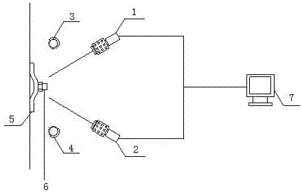
[0037] Such as figure 1 As shown, the present invention includes the following technical features: a first camera 1 , a second camera 2 , a first light source 3 , a second light source 4 , an anchor rod 5 , a pallet 6 , and a control computer 7 .

[0038] A kind of bolt pallet load visualization digital imaging method of the present invention, comprises the following steps:

[0039] Step 1: Install the pallet on the wall of the roadway, and then fix the anchor rod at the center of the pallet. When no pre-tightening force is applied, it is defined as the pallet before deformation, and after pre-tightening force is applied, it is defined as the deformed pallet;...


PUM


Abstract

The invention relates to an anchor rod pallet load visualization digital imaging method suitable for a non-contact measurement method of a stressed underground anchor rod. The anchor rod pallet load visualization digital imaging method specifically comprises the following steps: a plurality of images of a pallet before and after a deformation is shot using a CCD camera, space identification is performed on the multiple images of the pallet before and after the surface deformation through adoption of a digital speckle correlation technology, a three-dimensional coordinate is obtained through calculation, a three-dimensional model before and after the surface deformation of the pallet is established through fitting, and data before and after the surface deformation of the pallet are obtained; and a strain field is obtained through a rapid three-dimensional deformation analysis and comparison of the three-dimensional space data before and after the deformation of the pallet, a stress field is obtained through a combination with pallet bending rigidity, and a real-time load of an anchor rod can be obtained through integral back calculation of the stress field. Compared with a traditional strain foil, a traditional displacement sensor, a traditional anchor rod puller and a traditional hydraulic pillow, the anchor rod pallet load visualization digital imaging method is advantageous in that usage of a pallet load visualization digital imaging technology is simple and convenient, and three-dimensional deformation and strain measurement are achieved rapidly.

Description

technical field [0001] The invention relates to a visual digital imaging method for the anchor rod tray load, which is suitable for the non-contact measurement method of the stress of the anchor rod in underground mines and tunnels. Background technique [0002] Bolt is the most widely used support and reinforcement method in mining engineering. The purpose of bolt load observation is to analyze the load change of the bolt during the service period of the roadway, monitor the working state of the bolt, and provide actual measurements for adjusting and modifying support parameters. in accordance with. The bolt is installed in the borehole and is in a closed state, so it is impossible to directly observe its stress and strain. Traditional contact measurement methods, such as strain gauges, optical fiber sensors, displacement sensors, etc., have single functions, few measurement points, and limited data. And the shortcomings of large theoretical calculation errors; the non-con...

Claims


Application Information

Patent Timeline
Patent Type & Authority Applications(China)
IPC IPC(8): G01L1/24G01B11/16
CPCG01B11/16G01L1/24
Inventor 许兴亮王东杰田素川王志明孙大增刘青鑫刘忠堂宋志坚李俊生马晓健俞庆彬
Owner CHINA UNIV OF MINING & TECH
Why Eureka
Try Eureka