
Cone penetration measuring instrument

A measuring instrument and cone penetration technology, which is applied in the field of medical equipment, can solve the problems of test needle falling skew, speed interference, and the installation height of test needle cannot be guaranteed to be completely consistent, so as to achieve the effect of ensuring accuracy and convenient adjustment

Inactive Publication Date: 2017-11-07
王文乐
View PDF7 Cites 4 Cited by
  • Summary
  • Abstract
  • Description
  • Claims
  • Application Information

AI Technical Summary

Problems solved by technology

[0003] The existing instrument for testing cone penetration includes a frame body, a test needle is arranged on the frame body, and a test cone head is provided at the lower end of the test needle. The test needle is released from the limit and falls so that the test cone head falls into the test material. The depth of the taper is used to detect its hardness, but if the test needle shakes or the circumferential limit is uneven when the test needle is released from the limit, it is easy to make the test needle skew when it falls, causing the test cone to fall into the direction of the test material Skew, or non-circumferential release of the limit at the same time when the limit is released, and collide with the guide hole wall in the frame, so that the speed of the test cone falling into the test material is disturbed and the test result is affected. When testing multiple times, the test needle The installation height cannot be guaranteed to be exactly the same, and the speed at which the test cone falls into the test material will be disturbed, which will affect the test results

Method used


Image

  • Cone penetration measuring instrument
  • Cone penetration measuring instrument
  • Cone penetration measuring instrument

Examples


Embodiment Construction

[0019] Such as Figure 1~5 as shown,

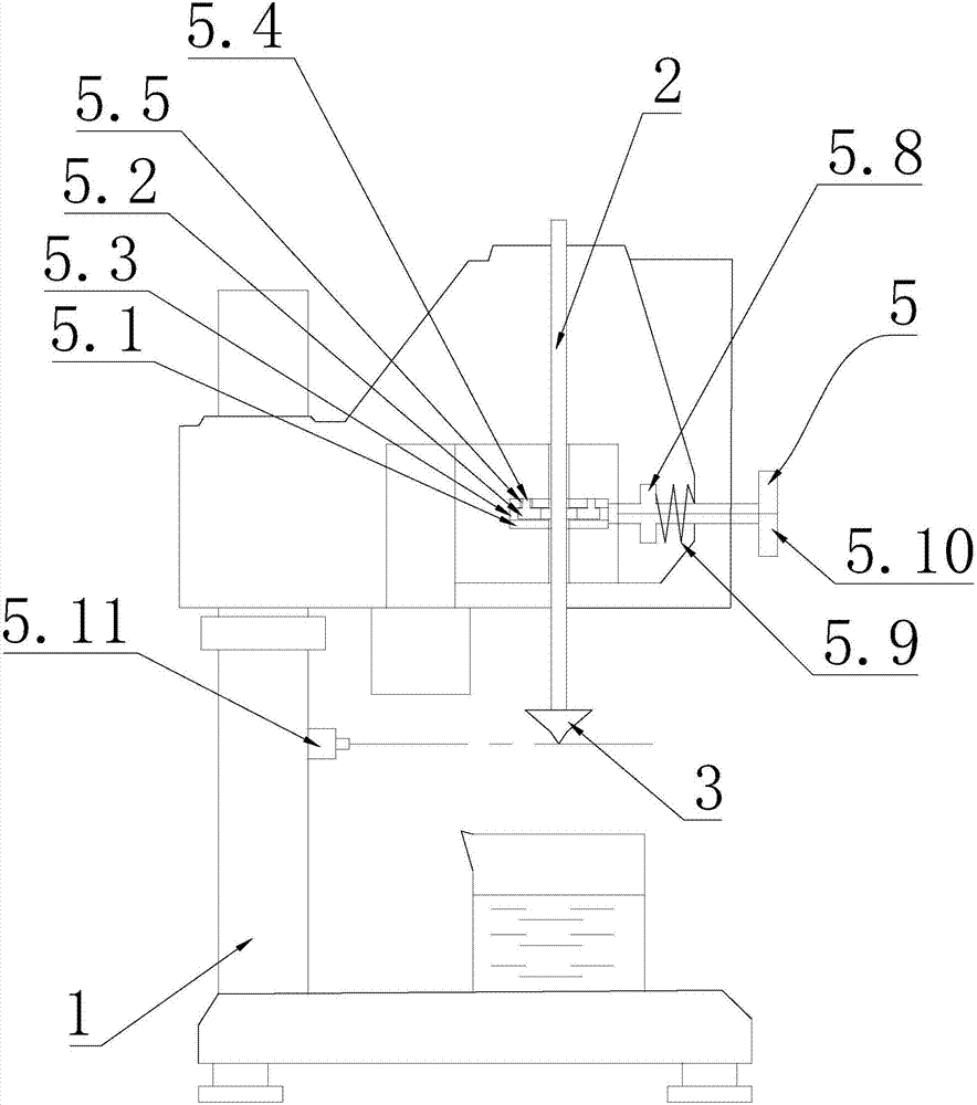
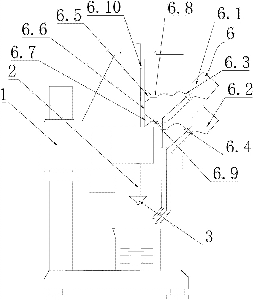
[0020] A cone penetration tester, comprising a frame body 1, a test needle 2 is arranged on the frame body 1, a test cone head 3 is arranged at the lower end of the test needle 2, and a test needle head 3 is provided at the lower end of the test needle body 1. 2 vertically drop into the guide hole 4 of the test material, characterized in that:

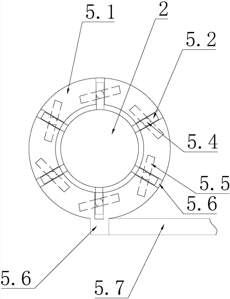
[0021] The cone penetration measuring instrument is provided with a limit structure 5 for simultaneously releasing the limit in the circumferential direction of the test needle 2,

[0022]The limit structure 5 includes a limit block 5.1 which is arranged on the upper end of the test needle 2 and protrudes at intervals in the circumferential direction. The frame body 1 is provided with a switch column 5.2, and the upper end of the switch column 5.2 is provided with a knob 5.2.1. The lower end of the switch column 5.2 is provided with a claw 5.2.2 for abutting against the lower end surface of the ...


PUM


Abstract

The invention discloses a cone penetration measuring instrument. The cone penetration measuring instrument comprises a rack body (1), wherein a test needle (2) is arranged on the rack body (1); a test cone head (3) is arranged at the lower end of the test needle (2); a guide hole (4) for allowing the test needle (2) to vertically drop into a test material is arranged in the rack body (1); the cone penetration measuring instrument is equipped with a limited structure (5) for allowing the test needle (2) to relieve limiting in the peripheral direction; the limited structure (5) comprises a limiting disc (5.1) which is arranged in the rack (1) and sleeves in the peripheral direction of the test needle (2); and a plurality of limited posts (5.2) which abut against the peripheral wall of the test needle are arranged in the peripheral direction in the limited disc (5.1) at intervals. The invention provides the cone penetration measuring instrument which relieves the limiting in the peripheral direction, so that the test needle drops, is not liable to tilt or is not liable to colloid with the guide hole, and speed, dropping into the test material, of the test cone head is consistent.

Description

technical field [0001] The invention relates to the technical field of medical instruments, in particular to a cone penetration measuring instrument. Background technique [0002] Cone penetration is an index to measure the consistency and hardness of grease. It refers to the depth of the cone falling into the sample under the specified load, time and temperature conditions. The larger the penetration value, the softer the test matrix material is, and vice versa. Ointment is a common dosage form of drugs for external use. Commonly used base materials include vaseline, lanolin, beeswax and other semi-solid substances. The measurement of viscosity has corresponding provisions. [0003] The existing instrument for testing cone penetration includes a frame body, a test needle is arranged on the frame body, and a test cone head is provided at the lower end of the test needle. The test needle is released from the limit and falls so that the test cone head falls into the test mat...

Claims


Application Information

Patent Timeline
IPC IPC(8): G01N11/12
CPCG01N11/12
Inventor 刘素萍
Owner 王文乐
Learn More