Cotton ball machine with impurity removal mechanism

A cotton ball machine and cotton ball technology are applied in the direction of medicine equipment, medicine equipment, other medical equipment, etc., which can solve the problems of product quality decline and confusion, and achieve the effect of eliminating static electricity.

Inactive Publication Date: 2017-11-10
苏加强
View PDF1 Cites 1 Cited by
  • Summary
  • Abstract
  • Description
  • Claims
  • Application Information

AI Technical Summary

Problems solved by technology

[0003] Therefore, the Chinese invention patent CN 206342614U discloses a multi-pipe cotton ball machine, which includes a cotton ball machine body, and the cotton ball machine body includes a housing. There is a guide wheel, a material inlet is provided under the guide wheel on the housing, a cotton cutting system is provided below the material inlet, and 4-12 long ball-making tubes are arranged in front of the cotton-breaking system, and the length of the ball making There are two rows of adjustment racks above the tube. The adjustment racks are respectively located near the cotton-feeding end and near the middle of the long ball-making tube. A conveyor belt is arranged below the long ball-making tube. There is a rough friction surface at 3-1 / 2, and the two ends of the ball-making long tube are provided with enlarged bell mouths, which can better realize the batch processing of cotton balls, but due to the impurities or dust mixed in the raw materials, it will cause the product to be damaged. decline in quality

Method used


Image

  • Cotton ball machine with impurity removal mechanism
  • Cotton ball machine with impurity removal mechanism
  • Cotton ball machine with impurity removal mechanism

Examples


Embodiment Construction

[0019] The following will clearly and completely describe the technical solutions in the embodiments of the present invention with reference to the accompanying drawings in the embodiments of the present invention. Obviously, the described embodiments are only some, not all, embodiments of the present invention. Based on the embodiments of the present invention, all other embodiments obtained by persons of ordinary skill in the art without making creative efforts belong to the protection scope of the present invention.

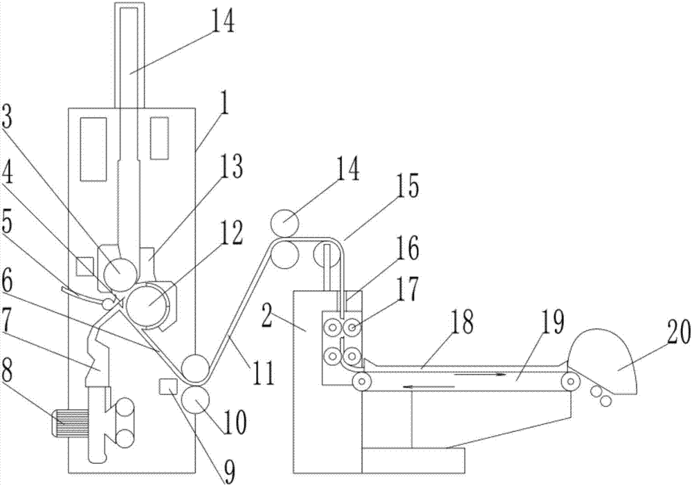
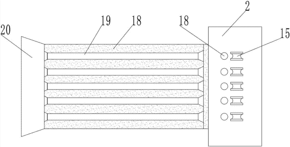
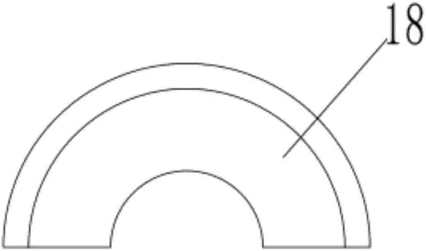
[0020] see Figure 1~3 , in an embodiment of the present invention, a cotton ball machine with an impurity removal mechanism includes an impurity removal box 1 and a cotton ball machine 2, and the impurity removal box 1 includes a cotton feeding roller 3, a dust removal knife 4, a negative pressure suction pipe 5, Down the cotton storage path 6, the cotton output roller 12 and the cotton path 14, the inside of the miscellaneous removal box 1 is provided with a...


PUM


Abstract

The invention discloses a cotton ball machine with an impurity removal mechanism, which comprises an impurity removal box and a cotton ball machine. The impurity removal box includes a cotton feeding roller, a dust removal knife, a negative pressure suction pipe, a lower cotton storage channel, a cotton outlet roller and a cotton ball machine. Cotton path, the inside of the trash removal box is provided with a cotton path, the bottom end of the cotton path is provided with a cotton feeding plate, the cotton feeding plate is equipped with a cotton feeding roller, and the lower end of the cotton path is provided with a lower cotton storage There is an opening roller installed on the top of the lower cotton storage channel, and a positive pressure blowpipe is installed on one side of the lower cotton storage channel. , and with the static elimination device, it can effectively eliminate the static electricity on the cotton sliver, preventing it from being wound on the cotton outlet roller due to electrostatic adsorption of impurities in the air or with the cotton outlet roller during the movement, and finally passing through the cotton ball pipe And the conveyor belt with rough surface kneads the sliver into a cotton ball for output.

Description

technical field [0001] The invention is specifically a cotton ball machine with an impurity removal mechanism. Background technique [0002] Medical cotton balls are a must-have medical product in medical units. They are used in large quantities. Most of the cotton balls are made by hand before use. When making them, the left hand presses the rolled medical absorbent cotton, and the right hand presses the rolled medical absorbent cotton. According to the size requirements of the cotton balls, tear off a small handful and put it in the left hand to hold the cotton, and tear off a small handful from the rolled medical absorbent cotton with the right hand according to the size requirements of the cotton balls and put it in the left hand to hold it until the left hand is full Later, move the dry cotton ball into the bottle and pour 75% medical alcohol for use. Cotton balls are used in a large amount in medical work, which requires more energy and physical strength of medical wo...

Claims


Application Information

Patent Timeline
IPC IPC(8): A61M35/00A61L2/18
CPCA61M35/006A61L2/18A61M2207/10
Inventor 苏加强
Owner 苏加强
Why Eureka
Try Eureka