Efficient sludge drying treatment device

A sludge drying and treatment device technology, applied in sludge treatment, water/sludge/sewage treatment, dehydration/drying/concentrated sludge treatment, etc. The effect of convenient discharge and novel structure

Pending Publication Date: 2017-11-10
ZHENGZHOU UNIV
15 Cites 11 Cited by

AI-Extracted Technical Summary

Problems solved by technology

[0003] At present, the traditional dehydration treatment device has a rigid structure and low efficiency. Therefore, it is of great positive signific...

Abstract

The invention discloses an efficient sludge drying treatment device. The efficient sludge drying treatment device comprises a casing, wherein support legs are bilaterally symmetrically arranged at the bottom of the casing; a screen is arranged in the casing and is inclined; a vertical rod is hinged with the bottom end of the left side of the screen; the bottom end of the vertical rod is fixed at the bottom in the casing; a feeding port is formed in the position, above a guide plate, of the top end of the right side of the casing; a cushion block is fixed at the bottom of the right end of the screen; a rotary cam is arranged below the cushion block. The efficient sludge drying treatment device is novel in structure; with ingenious arrangement of the screen and a screen vibration drive mechanism, dehydration efficiency is greatly improved, meanwhile, scrapers are arranged above the screen and perform reciprocating motion, and sludge on the screen is turned over vertically, so that the dehydration and drying efficiency is further improved; a pair of extrusion rolls is further arranged and used for thoroughly dehydrating and drying the sludge; a discharging mechanism is arranged to facilitate discharging.

Application Domain

Technology Topic

Image

  • Efficient sludge drying treatment device
  • Efficient sludge drying treatment device
  • Efficient sludge drying treatment device

Examples

  • Experimental program(1)

Example Embodiment

[0018] The technical solutions in the embodiments of the present invention will be clearly and completely described below in conjunction with the accompanying drawings in the embodiments of the present invention. Obviously, the described embodiments are only a part of the embodiments of the present invention, rather than all the embodiments. Based on the embodiments of the present invention, all other embodiments obtained by those of ordinary skill in the art without creative work shall fall within the protection scope of the present invention.
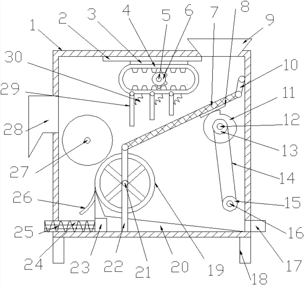
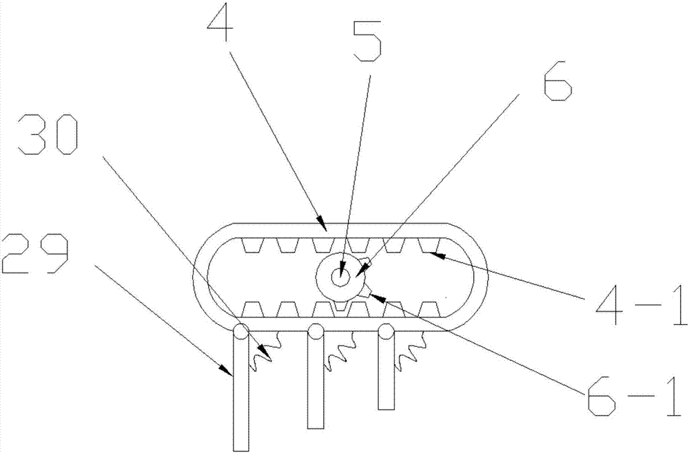
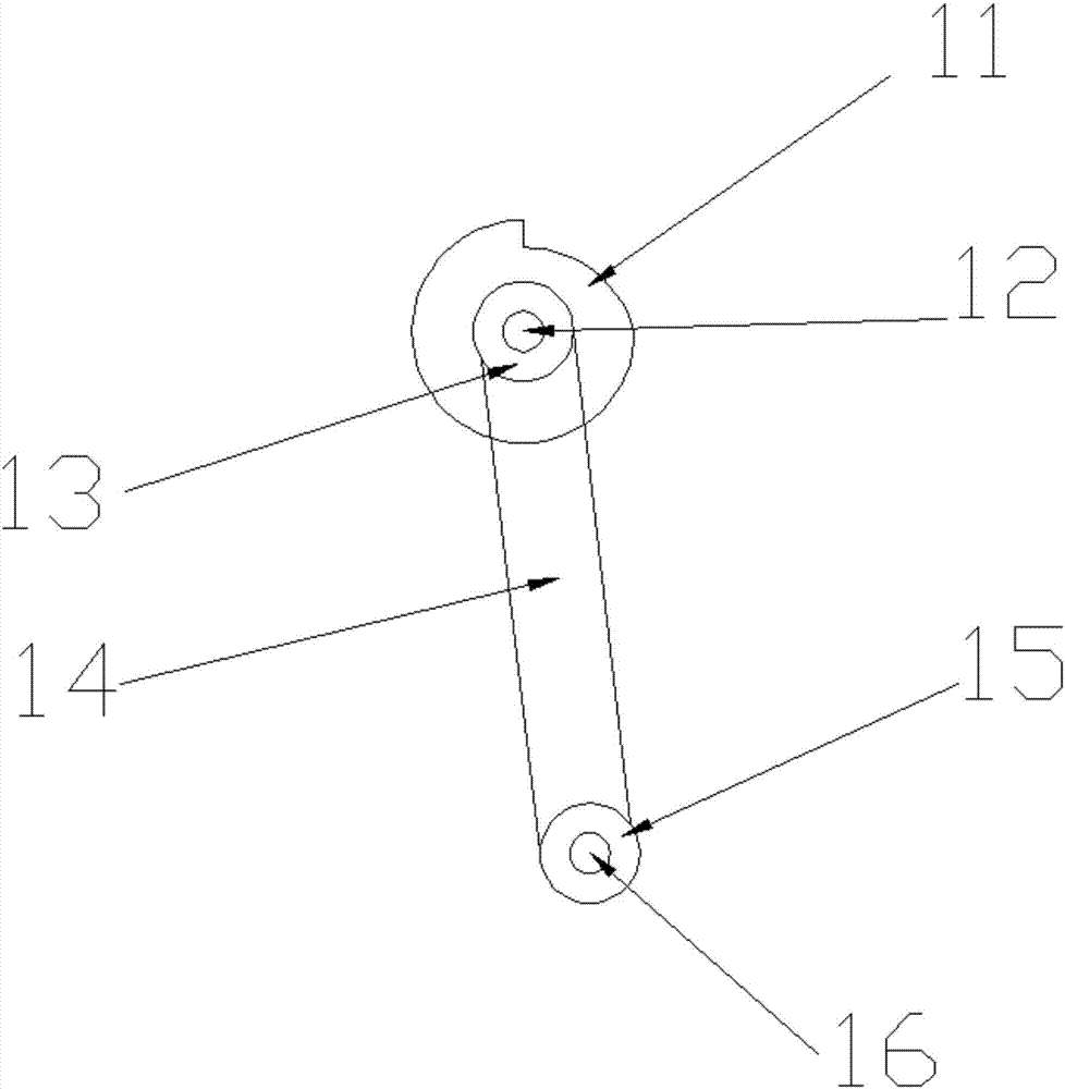
[0019] See Figure 1~3 In the embodiment of the present invention, a high-efficiency sludge drying treatment device includes a casing 1, and the bottom of the casing 1 is provided with supporting feet 18 symmetrically, and the casing 1 is provided with a screen 7, the screen 7 It is arranged obliquely, the bottom end of the left side of the screen 7 is hinged with a vertical rod 22, the bottom end of the vertical rod 22 is fixed to the inner bottom of the housing 1, and the top of the screen 7 is hingedly connected with a deflector 10, the deflector The top of 10 is fixed on the top side wall of the inner right side of the shell 1 by a hinge; the top of the right side of the shell 1 is provided with a feed port 9 above the baffle 10, and the top of the shell 1 is provided above the screen 7 The horizontal guide rail 2 is fitted with a slider 3, the lower side of the slider 3 is fixedly connected with a rectangular gear ring 4, the two ends of the rectangular gear ring 4 are arc-shaped, and the inner side of the rectangular gear ring 4 is arranged symmetrically up and down. The rack 4-1, the rectangular ring gear 4 is sheathed with a drive gear 6, the drive gear 6 is a special-shaped gear, the drive gear 6 includes a disc body, the outer side of the disc body is provided with a third ring gear Rail 6-1; a drive shaft 5 is sleeved in the middle of the drive gear 6, and the drive shaft 5 is sleeved on a bearing provided on a corresponding side wall of the housing, and the drive shaft 5 is driven by a drive motor provided on the outside of the housing. A plurality of scrapers 29 are fixedly arranged under the rectangular gear ring 4, and the scrapers 29 are evenly spaced from left to right, and the height of the scrapers 29 gradually decreases. The top end of the scraper 29 is hingedly connected with the rectangular gear ring 4; A torsion spring 30 is connected between the top of the scraper 29 and the rectangular ring gear 4; a cushion block 8 is fixedly disposed at the bottom of the right end of the screen 7, and a rotating cam 11 is disposed under the cushion block 8, and the rotating cam 11 is sleeved On the vibrating shaft 12 provided in the housing below the spacer 8, both ends of the vibrating shaft 12 are sleeved in bearings provided on the corresponding side walls of the housing 1, and a driven pulley 13 is fixedly provided on the side of the rotating cam 11 , The inner bottom end of the housing 1 is fixedly provided with a driving pulley 15, the driving pulley 15 and the driven pulley 13 are connected by a belt 14, and the driving pulley 15 is fixed on the outer side wall of the housing The provided vibration motor is driven by the transmission shaft 16. The upper squeeze roller 17 and the lower squeeze roller 21 are provided on the left side of the screen 7. The lower squeeze roller 21 includes an outer roller 19, which is a filter Mesh cylinder; the bottom of the casing 1 below the lower squeeze roller 21 is provided with a diversion bin 20, the diversion bin 20 is an L-shaped shell structure, the right top of the diversion bin 20 abuts the left end of the lower squeeze roller 21 Part, the left side of the housing 1 is provided with a discharging channel 24, the discharging channel 24 is provided with a screw discharging shaft 25, the screw discharging shaft 25 is provided by a discharging motor set in the diversion bin 20 23 drive; the left side of the diversion bin 20 is provided with an arc baffle 26 corresponding to the discharge channel 24, which slows down the speed of the dried sludge block and avoids directly hitting the screw discharge shaft 25; the bottom of the right side of the housing 1 corresponds to A liquid outlet 17 is provided at the bottom of the diversion chamber 20.
[0020] The working principle of the present invention is: the sludge falls onto the screen 7 through the inlet 9 through the deflector and is dehydrated. The rotating shaft 16 drives the driving pulley to rotate, and the driving pulley drives the driven pulley to rotate through the belt. The pulley drives the rotary cam to rotate around the vibrating shaft, and the rotation of the rotary cam drives the top of the screen to vibrate up and down, which greatly improves the efficiency of dehydration. The sludge falls along the screen, and the upper and lower squeeze rollers are further completely dehydrated; The outer drum 19 of the pressure roller 21 is a filter screen tube, and the filtered water directly flows down from the filter screen tube through the diversion bin and flows out from the liquid outlet 17, and the dehydrated and dried sludge flows between the upper squeeze roller and the lower squeeze roller. After falling through the baffle and decelerating, it enters the discharge pipe. The screw discharge shaft is driven to rotate by the discharge motor to push the dehydrated and dried sludge to be discharged from the discharge channel; while the sludge moves down the screen, the gear is driven The rotation drives the rectangular gear ring to reciprocate left and right, and the rectangular gear ring drives the scraper to reciprocate left and right above the screen, turning the sludge on the screen up and down to further improve the dehydration and drying efficiency.

PUM

no PUM

Description & Claims & Application Information

We can also present the details of the Description, Claims and Application information to help users get a comprehensive understanding of the technical details of the patent, such as background art, summary of invention, brief description of drawings, description of embodiments, and other original content. On the other hand, users can also determine the specific scope of protection of the technology through the list of claims; as well as understand the changes in the life cycle of the technology with the presentation of the patent timeline. Login to view more.

Similar technology patents

Classification and recommendation of technical efficacy words

  • Novel structure
  • Improve dehydration efficiency

Digital controlled temp. regulating automatic water tap

InactiveCN101000111ANovel structureRealize the automation of water temperature adjustmentOperating means/releasing devices for valvesMultiple way valvesAutomatic faucetElectricity
Owner:宁波意耐特阀门有限公司

Environment-friendly-type polluted oil processing agent

ActiveCN103820142AImprove dehydration efficiencyFor the purpose of separationDewatering/demulsification with chemical meansDewatering/demulsification with electric/magnetic meansSolventAluminium salts
Owner:SHAANXI RES DESIGN INST OF PETROLEUM CHEM IND

Novel crushing and dehydrating feed processing equipment

InactiveCN105618213AImprove cutting and crushing efficiencyImprove dehydration efficiencyFeeding-stuffGrain treatmentsFeed processingEngineering
Owner:AGRI PROD PROCESSING INST GUANGXI ACADEMY OF AGRI SCI
Why Eureka
Try Eureka