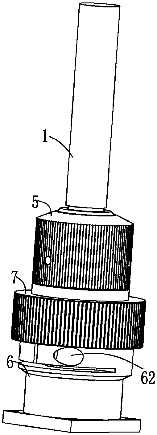
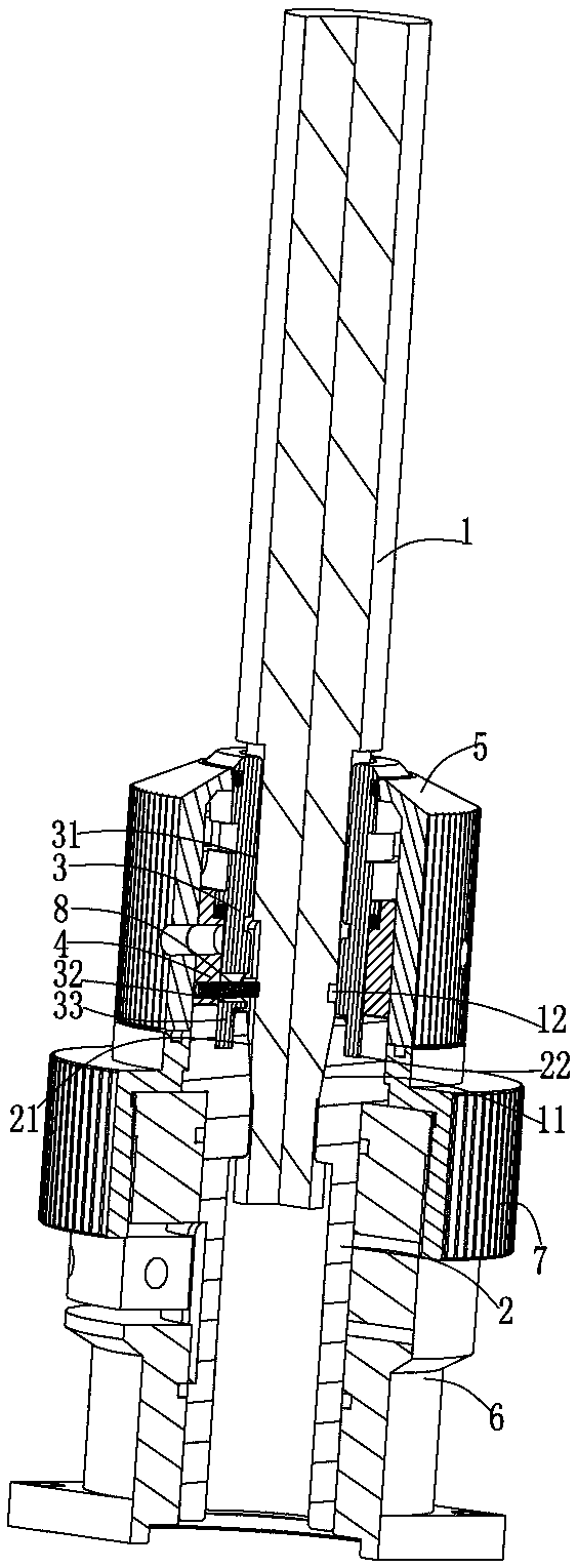
Mechanism used for positioning and locking of QBH optical fiber head and cutting head

A technology of optical fiber head and cutting head, which is applied in the direction of welding/welding/cutting objects, laser welding equipment, manufacturing tools, etc. The problems such as poor cutting quality of the machine can be solved, and the effect of convenient and fast installation and connection, high quality cutting products, and reduced replacement and maintenance time can be achieved.

Pending Publication Date: 2017-11-10
DONGGUAN GLORYSTAR LASER TECH
View PDF6 Cites 2 Cited by
  • Summary
  • Abstract
  • Description
  • Claims
  • Application Information

AI Technical Summary

Problems solved by technology

[0004] However, the existing laser cutting machine using QBH fiber optic head and the locking and positioning of QBH fiber optic head and cutting head have the following shortcomings: First, the replacement and maintenance of the existing fiber laser cutting head using QBH fiber optic head is very cumbersome and time-consuming The second is that the connection between the QHB fiber optic head and the cutting head is not well positioned, and the connection is easy to loose. The QBH fiber optic head is installed on the machine tool and shakes, making the laser cutting machine unable to obtain stable incident light, and the cutting quality of the laser cutting machine is not good. The third is that the existing laser cutting machine lacks an effective structure or product for fast and reliable locking and positioning of the QBH fiber optic head and cutting head

Method used


Image

  • Mechanism used for positioning and locking of QBH optical fiber head and cutting head
  • Mechanism used for positioning and locking of QBH optical fiber head and cutting head
  • Mechanism used for positioning and locking of QBH optical fiber head and cutting head

Examples


Embodiment Construction

[0027] The present invention will be described in further detail below in conjunction with the accompanying drawings.

[0028] The embodiments described by referring to the figures are exemplary and are intended to explain the present application and should not be construed as limiting the present application. In the description of the present application, it should be understood that the terms "center", "longitudinal", "transverse", "length", "width", "thickness", "upper", "lower", "front", " Orientation or position indicated by "back", "left", "right", "vertical", "horizontal", "top", "bottom", "inner", "outer", "clockwise", "counterclockwise", etc. The relationship is based on the orientation or positional relationship shown in the drawings, and is only for the convenience of describing the present application and simplifying the description, rather than indicating or implying that the referred device or element must have a specific orientation, be constructed and operated ...


PUM


Abstract

The invention discloses a mechanism used for positioning and locking of a QBH optical fiber head and a cutting head. The mechanism comprises a QBH optical fiber head and a locking and positioning mechanism arranged on the cutting head. A frustum is arranged at one end of the QBH optical fiber head, and the position, closely abutting against the frustum, of the QBH optical fiber head is provided with a slot. The locking and positioning mechanism comprises a lower positioning ring, an upper positioning ring, a locking ring and a rotary knob. A conical hole which is used for insertion of the QBH optical fiber head in a matched manner and is in clearance fit with the frustum is formed in the lower positioning ring. The upper positioning ring is arranged at the upper end of the lower positioning ring, and an arc groove is formed in the circumferential side wall of the upper positioning ring. The locking ring is arranged on the outer side of the upper positioning ring, the position, matched with the arc groove, of the locking ring is provided with a pin shaft, and the pin shaft penetrates the matched arc groove and inwards stretches into the upper positioning ring. The rotary knob is arranged on the outer side of the locking ring and can drive the locking ring and the pin shaft to rotate, the pin shaft slides along the matched arc groove and is locked in the slot of the QBH optical fiber head inserted in the lower positioning ring, and the QBH optical fiber head is locked. According to the mechanism, rapid and reliable locking and positioning of the QBH optical fiber head and the cutting head can be achieved, and rapid dismounting and mounting are achieved.

Description

technical field [0001] The invention relates to the technical field of laser cutting, in particular to a mechanism for positioning and locking a QBH optical fiber head and a cutting head. Background technique [0002] In recent years, the domestic demand for laser cutting machine tools has increased rapidly. Fiber laser cutting machine tools have many advantages such as easy maintenance, low consumption cost, and excellent cutting section, so the growth in demand is particularly prominent. As an important component of the fiber laser cutting machine, the fiber laser cutting head directly affects the cutting quality of the fiber laser cutting machine. [0003] QBH fiber optic head is a standard fiber optic head. Existing laser cutting machines often use QBH fiber optic head as the light output connector, and the laser light emitted by the laser generator of the laser cutting machine is transmitted to the QHB fiber optic head through a flexible optical fiber, and the laser be...

Claims


Application Information

Patent Timeline
Patent Type & Authority Applications(China)
IPC IPC(8): B23K26/38B23K26/70B23K101/32
CPCB23K26/38B23K26/702B23K2101/32
Inventor 姚玉东尹怀化何忠宝郝英锋李荣飞刘南麟
Owner DONGGUAN GLORYSTAR LASER TECH
Why Eureka
Try Eureka