Addition and reduction material composite machining center

A compound machining center and machining center technology, which is applied in the field of mechanical processing, can solve problems such as unsatisfactory use effects, and achieve ideal use effects, good processing quality, and high processing efficiency.

Active Publication Date: 2017-11-10
HAIXI (FUJIAN) INST CHINA ACAD OF MASCH SCI&TECH GRP
View PDF6 Cites 27 Cited by
  • Summary
  • Abstract
  • Description
  • Claims
  • Application Information

AI Technical Summary

Problems solved by technology

[0004] In the actual production of some high-end products, such as aerospace precision manufacturing and testing, vehicle intelligent manufacturing, maintenance and control technology research, and the establishment and improvement of aviation and vehicle equipment manufacturing research platforms, it is sometimes difficult to complete only through subtractive or additive processing. For the processing of parts with specific shapes, it is necessary to process the intermediate parts first, and then further reduce the material and finish the intermediate parts to obtain the final product, and some parts need to be alternately processed by local additive and subtractive processing to achieve the final precision. Requirements, this requires the use of the additive machining center and the subtractive machining center respectively, and two or more times of clamping and positioning calibration are required, which inevitably produces positional errors caused by two or more separate clampings, and the use effect not ideal

Method used


Image

  • Addition and reduction material composite machining center

Examples


Embodiment Construction

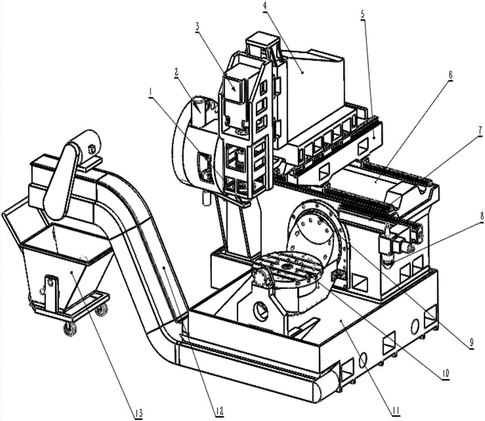
[0014] Embodiments of the present invention, such as figure 1 As shown, a compound machining center for adding and subtracting materials includes a five-axis subtractive machining center and a laser additive printing device; the five-axis subtractive machining center includes a square base 11 and a bed 6 on the rear of the top surface of the base 11 , the bed saddle 5 that is erected on the bed 6 through the guide rails laid in the X axis, the ram 4 that is erected on the saddle 5 through the guide rails laid in the Y axis, and the ram 4 that is erected on the bed saddle 5 through the guide rails laid in the Z axis. The spindle box 3 on the front side of the pillow 4, the spindle 1 located in the spindle box 3, the tool magazine 2 located on the left side of the spindle box 3; a workpiece clamping platform is arranged between the front side of the bed 6 and the top of the base 11, The workpiece clamping platform is provided with a rotary C-axis 10 vertically arranged on the ro...


PUM


Abstract

The invention discloses an addition and reduction material composite machining center which comprises a five-axis reduction material machining center and a laser addition material printing device. The five-axis reduction material machining center comprises a base, a bed body arranged on the rear portion on the top face of the base, a saddle erected on the bed body through a guide rail, a sliding pillow erected on the saddle through the guide rail, a main shaft box erected on the front side of the sliding pillow through the guide rail, a main shaft arranged in the main shaft box, and a tool magazine arranged on the left side face of the main shaft box. A clamping table is arranged between the front side of the bed body and the portion above the base. The clamping table is provided with a revolution shaft C. The clamping table is movably connected with the front side face of the bed body through a revolution shaft B. The laser addition material printing device comprises a laser printing head movably erected on the bed body. The laser printing head is connected with the bed body through an installing module which can be controlled to move and controlled to be disassembled. A clamping handle matched with the main shaft is arranged on the top of the laser printing head. Dual use of one machine is achieved, the space coordinate system of one position degree is shared, errors of the position degree are small, machining is flexible, machining quality is good, and efficiency is high.

Description

technical field [0001] The invention belongs to the technical field of mechanical processing, and in particular relates to a compound machining center for adding and subtracting materials. Background technique [0002] The most traditional method of mechanical processing is to use various machine tools and machining centers to perform various types of material reduction processing on billets to obtain predetermined shapes and sizes. [0003] The emergence of rapid prototyping technology has brought a new approach to machining, that is, through the melting and accumulation of materials, that is, additive processing, to obtain predetermined shapes and sizes. [0004] In the actual production of some high-end products, such as aerospace precision manufacturing and testing, vehicle intelligent manufacturing, maintenance and control technology research, and the establishment and improvement of aviation and vehicle equipment manufacturing research platforms, it is sometimes diffic...

Claims


Application Information

Patent Timeline
Patent Type & Authority Applications(China)
IPC IPC(8): B23P23/04
CPCB23P23/04Y02P10/25
Inventor 刘文志姜超侯亮林锦明梁英
Owner HAIXI (FUJIAN) INST CHINA ACAD OF MASCH SCI&TECH GRP
Why Eureka
Try Eureka