
Integrated slag discharge device for drill carriage

An all-in-one, drilling rig technology, applied in drilling, drilling equipment, earth-moving drilling with mechanical conveying devices, etc., can solve the problem that pulverized coal needs to be cleaned manually, so as to reduce the labor intensity of employees, improve work efficiency, The effect of the overall structure is simple

Inactive Publication Date: 2017-11-10
淄博中安工程技术有限责任公司
View PDF0 Cites 2 Cited by
  • Summary
  • Abstract
  • Description
  • Claims
  • Application Information

AI Technical Summary

Problems solved by technology

[0003] The present invention aims at the technical defects of the prior art, and provides an integrated slagging device for the drilling rig, so as to solve the problem in the prior art that the pulverized coal produced by the large-diameter pressure relief drilling needs to be cleaned manually

Method used


Image

  • Integrated slag discharge device for drill carriage
  • Integrated slag discharge device for drill carriage
  • Integrated slag discharge device for drill carriage

Examples


Embodiment 1

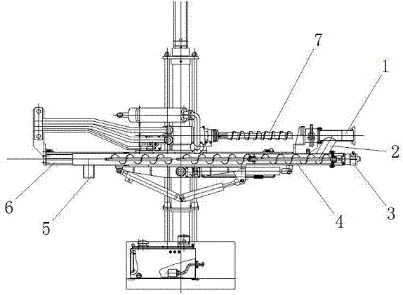
[0021] An integrated slag discharge device for drilling rigs, such as figure 1 As shown, the device includes a pulverized coal collection cylinder 1, a connecting cylinder 2, an air motor 3, a screw conveyor 4, and a pulverized coal outlet 5, wherein one end of the screw conveyor 4 is connected to the connecting cylinder 2, and the other end of the screw conveyor 4 There is a pulverized coal outlet 5 below the pulverized coal collection cylinder 1 connected to the upper end of the connection cylinder 2, the pulverized coal collection cylinder 1 is in a horizontal state, the air motor 3 is connected to the screw conveyor 4, and the rotating shaft of the air motor 3 is connected to the screw conveyor. The screws of the conveyor 4 are connected.

[0022] The state when the device is applied to the CMQS1-400 / 5.2S deep hole pneumatic drilling rig is as follows figure 2 As shown, the device as a whole is fixedly connected to the drilling car guide rail 6 places, and simultaneously...

Embodiment 2

[0025] An integrated slag discharge device for drilling rigs, such as image 3 As shown, it includes a pulverized coal collection cylinder 1, a connecting cylinder 2, an air motor 3, a screw conveyor 4, and a pulverized coal outlet 5, wherein one end of the screw conveyor 4 is connected to the connecting cylinder 2, and the other end of the screw conveyor 4 is connected below There is a pulverized coal outlet 5, the pulverized coal collection cylinder 1 is connected to the upper end of the connection cylinder 2, the pulverized coal collection cylinder 1 is in a horizontal state, the air motor 3 is connected to the screw conveyor 4, and the rotating shaft of the air motor 3 is connected to the screw conveyor 4 screws are connected.

[0026] On the basis of the above technical solutions, the following conditions are met:

[0027] The angle between the axis of the connecting cylinder 2 and the axis of the screw conveyor 4 is 60°.

[0028] The pulverized coal outlet 5 is a cylin...


PUM


Abstract

The invention provides an integrated slag discharge device for drilling rigs, the pulverized coal collecting cylinder of the device can collect the pulverized coal produced during construction; the connecting cylinder transfers the pulverized coal to the screw conveyor; the air motor Provide power for the screw conveyor to push the pulverized coal to the tail end of the screw conveyor; it is discharged from the pulverized coal outlet at the tail end of the screw conveyor. When in use, the device can be fixedly connected to the drilling rig, and one end of the pulverized coal collection tube is attached to the coal wall to be drilled. Drilling action is performed, and the powder produced can be discharged in a centralized manner through the above working principle. The present invention has simple overall structure, convenient transformation, good stability and high reliability. The application of the present invention can effectively solve the problem that the coal dust produced in the large-diameter pressure relief drilling needs to be manually cleaned, thereby reducing the labor intensity of workers and improving work efficiency.

Description

technical field [0001] The invention relates to the technical field of mining equipment, in particular to an integrated slag discharge device for a drilling rig. Background technique [0002] Large-diameter borehole pressure relief is the most common and effective means of pressure relief. Taking Tangkou Coal Industry Company as an example, the average annual pressure relief project is more than 160,000 m3, and a large amount of coal will be discharged during the construction of large-diameter boreholes. The average size of each drill hole is 1.5m3, and 240,000 m3 of coal dust is produced throughout the year. Currently, coal dust is cleaned manually, which is time-consuming and labor-intensive. Contents of the invention [0003] The present invention aims at the technical defects of the prior art, and provides an integrated slag discharge device for the drilling rig, so as to solve the problem in the prior art that the pulverized coal produced in the large-diameter pressur...

Claims


Application Information

Patent Timeline
IPC IPC(8): E21B21/015E21B7/02
CPCE21B21/015E21B7/005E21B7/02
Inventor 刘延生任文涛刘志刚张惟昭崔保阁张金魁李杨杨高翔李锦秀
Owner 淄博中安工程技术有限责任公司
Learn More