Drive unit

一种驱动装置、驱动轴的技术,应用在传动装置、动力装置、电动力装置等方向,能够解决行驶稳定性恶化、差动用马达控制性繁琐、左右的驱动轮旋转等问题,达到提高行驶稳定性的效果

Active Publication Date: 2017-11-10
TOYOTA JIDOSHA KK +1
View PDF6 Cites 6 Cited by
  • Summary
  • Abstract
  • Description
  • Claims
  • Application Information

AI Technical Summary

Problems solved by technology

Therefore, when the torque vector distribution device is mounted on a vehicle, the left and right drive wheels are likely to rotate relative to each other due to a difference in the coefficient of friction between the left and right drive wheels and the road surface, or external disturbances such as unevenness of the road surface.
If the left and right drive wheels rotate relative to each other unexpectedly, there is a possibility that the running stability will deteriorate when driving straight.
On the other hand, if the differential motor is controlled to suppress unexpected relative rotation of the left and right drive wheels, the controllability of the differential motor becomes cumbersome, or there may be problems caused by rotation output from the differential motor. Possibility of vibration due to moment variation

Method used


Image

  • Drive unit
  • Drive unit
  • Drive unit

Examples


Embodiment Construction

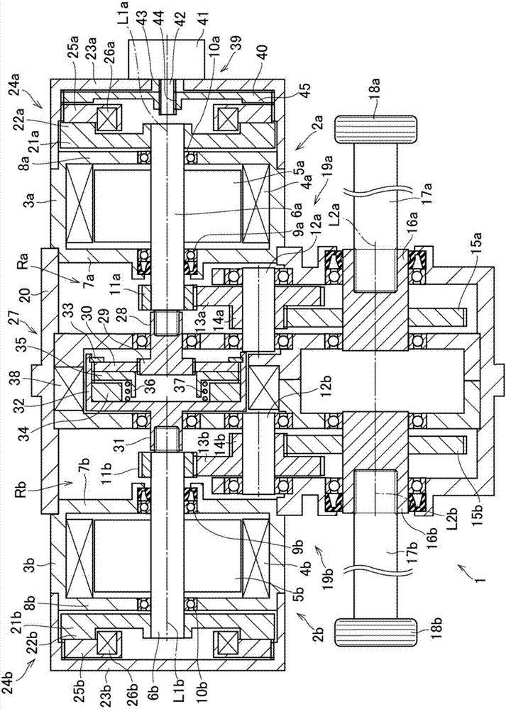
[0020] figure 1 An example of a driving device that can be used as an object of the present invention is shown. figure 1 The drive device 1 shown is mounted on a vehicle, and has a substantially symmetrical shape on both sides with a center portion in the vehicle width direction interposed therebetween. Therefore, in the following description, the structure of one side (the right side in the figure) will be described, and the structure of the other side will only be described for parts that are different from the structure of one side, and the structure of other parts will be omitted. instruction of. In addition, regarding the structure that is the same on one side and the other side, in the drawings, "a" is attached to the reference numerals of the components on one side, and "b" is attached to the reference numerals of the components on the other side, and, In the following description, when it is necessary to distinguish between the parts on one side and the parts on the ...


PUM


Abstract

A drive unit a drive unit which can prevent an occurrence of an unintentional relative rotation between the right and the left wheels is provided. The drive unit comprises: a first motor (2a)connected to the first driveshaft (17a)in a manner of transmitting a torque and a second motor (2b) connected to the second drive shaft (17b) in a manner of transmitting a torque; a first torque transmitting route (Ra) between the first motor and the first drive shaft; a second torque transmitting route (Rb) between the second motor and the second drive shaft; a first rotary member (6a) arranged in the first torque transmitting route; a second rotary member arranged in the second torque transmitting route; and a restriction device that restricts a differential rotation between the first rotary member and the second rotary member.

Description

technical field [0001] The present invention relates to a drive device configured to make it possible to vary the torques of drive shafts connected to left and right drive wheels. Background technique [0002] Patent Document 1 describes a torque vectoring device comprising a differential mechanism that transmits the output torque of a driving motor to the left and right drive wheels, and a torque vectoring mechanism that transmits the torque transmitted from the differential mechanism to the left and right wheels. It is composed of a differential motor that controls the distribution ratio. The differential mechanism is composed of two single-pinion planetary gear mechanisms, and torque is transmitted from the driving motor to each sun gear. Connected to a ring gear. Further, the drive wheel is connected to the carrier of each planetary gear mechanism via a drive shaft. [0003] Patent Document 1: International Publication No. 2015 / 008661 [0004] In the torque vector di...

Claims


Application Information

Patent Timeline
Patent Type & Authority Applications(China)
IPC IPC(8): F16H48/10F16H48/38
CPCF16H48/10F16H48/38F16H2048/102B60K1/00B60K1/02B60K17/046B60K23/04B60K2023/043F16D55/2262F16D65/186F16D2121/20F16H1/28F16D65/18F16H48/36
Inventor 矶野宏杉谷伸芳久保爱三
Owner TOYOTA JIDOSHA KK
Why Eureka
Try Eureka