Target spatial intersection measurement method for full-view scanning and measuring system

A measurement system and space rendezvous technology, applied in the direction of measurement devices, optical devices, instruments, etc., can solve the problems of splicing image errors, the inability to measure the surface information of large components or equipment, and the limited measurement range, etc., to achieve high precision.

Active Publication Date: 2017-11-10
AVIC BEIJING CHANGCHENG AVIATION MEASUREMENT & CONTROL TECH INST +1
View PDF7 Cites 9 Cited by
  • Summary
  • Abstract
  • Description
  • Claims
  • Application Information

AI Technical Summary

Problems solved by technology

Manual measurement with jigs is simple in operation and low in cost. It is a measurement method widely used in production at present, but the measurement efficiency is low and the accuracy is poor.
The three-coordinate measuring machine is a general-purpose equipment for three-coordinate measurement. It has good measurement accuracy, but the measurement range is limited.
Laser tracker, 3D laser rangefinder, total station and theodolite are suitable for general site conditions, but generally have small field of view and low measurement efficiency, and can only achieve single-point measurement at a time, and cannot achieve surface information of large components or equi

Method used


Image

  • Target spatial intersection measurement method for full-view scanning and measuring system
  • Target spatial intersection measurement method for full-view scanning and measuring system
  • Target spatial intersection measurement method for full-view scanning and measuring system

Examples


Embodiment Construction

[0030] The specific implementation manner of the present invention will be described in detail below with reference to the drawings and embodiments.

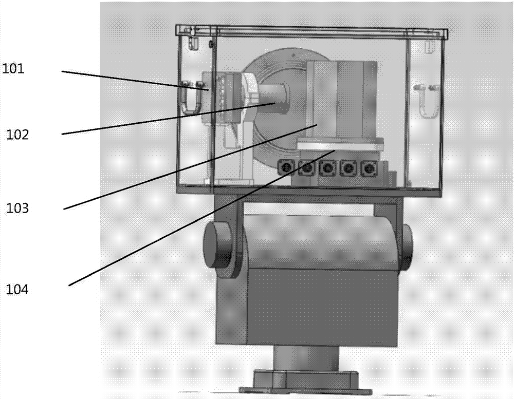
[0031] The full-view scanning measurement system includes a target, a measurement station, and a three-dimensional coordinate acquisition module in space. figure 1 It shows the structural diagram of the full viewing angle scanning measurement system of the embodiment of the present invention. Such as figure 1 As shown, the measuring station is composed of an octagonal mirror drum 103, a single-axis turntable 104, a line scan camera 102, an f-θ optical lens 101, and an image processing module.

[0032] Since each measurement station can scan the measurement field within 90 degrees in the horizontal direction and 90 degrees in the vertical direction, at least two scanning measurement workstations are required. When arranging these workstations, it is necessary to carefully adjust their positions so that they can be placed just t...


PUM


Abstract

The invention discloses an external parameter space intersection measurement method for a full-view scanning and measuring system. The full-view scanning and measuring system comprises at least two measurement stations. Each measurement station adopts a polygon prism drum as a scanning rotating mirror to synchronously scan and obtain an image of the same measured target in the overall space of a measurement field which is facing to the measurement station. The method comprises the following steps of processing obtained images to obtain the image pixel coordinates of a target in the coordinate system of each measurement station; according to the image pixel coordinates, calculating the azimuth angle information of the same measured target relative to each measurement station; calibrating the external parameters of the system and resolving the three-dimensional coordinates of the azimuth angle information of the same measured target relative to each measurement station through correcting a measurement model by adopting the external parameters; and obtaining the spatial three-dimensional coordinate value of the measured target in the spatial coordinate system of the above system after the calibration process of the external parameters of the system. According to the above method, the measurement model is compensated by adopting external parameters. Therefore, the measured three-dimensional coordinates of the target are high in precision.

Description

technical field [0001] The invention relates to the technical field of measurement of three-dimensional coordinates in space, in particular to a target space intersection measurement method for a full-view scanning measurement system. Background technique [0002] With the rapid advancement of national important projects such as large aircraft, manned spaceflight and large radar, the real-time monitoring technology for the deformation of large parts and equipment and the movement status of objects in large spaces has been rapidly developed. The increasing perfection of computer technology, electronic technology, and optical technology, as well as the continuous progress of image processing, pattern recognition and other technologies have gradually provided certain support for the monitoring of large-scale components and equipment status information. [0003] At present, the state detection of large components and equipment mainly includes two types: contact type and non-cont...

Claims


Application Information

Patent Timeline
IPC IPC(8): G01B11/00
CPCG01B11/002
Inventor 杨超张卫攀马燕飞张华黄勇麻彦轩
Owner AVIC BEIJING CHANGCHENG AVIATION MEASUREMENT & CONTROL TECH INST
Why Eureka
Try Eureka