Variable line structure light guide plate and optical module

A light guide plate and line technology, applied in the field of optics, can solve problems such as dot duplication, unsatisfaction, mesh collision interference, etc., and achieve the effects of benefiting printing stability, avoiding dot interference texture, and reducing the use of covering films

Pending Publication Date: 2017-11-10
深圳市超显科技有限公司
View PDF11 Cites 2 Cited by
  • Summary
  • Abstract
  • Description
  • Claims
  • Application Information

AI Technical Summary

Problems solved by technology

[0005] 1. Due to the limitation of printing plate-making precision, in the process of making small dots, the dots cannot be copied with high precision, resulting in the fact that the actual printed dots cannot match the preset design, resulting in obvious texture traces during the dot change process, which affects the appearance of the light guide plate
Therefore, the existing design process cannot satisfy the production of light guide plates with a light guide point diameter of less than 0.2mm, and cannot produce thinner light guide plates.
[0006] 2. Due to the cross-arranged dot structure design, it is easy to cause mesh collision interference during the plate-making process, forming a regular pattern, which has a great impact on the plate-making yield
[0007] 3. Due to the large dot shape and structure, the existing printed dot structure light guide plate needs to use 3 or more diffusion film structures to cover the dot shape in the practical application of the module, and the overall cost of the module is relatively high
[0008] 4. Due to the high requirements for dot restoration, in the actual printing process, poor dot printing will lead to a high defective rate of finished products

Method used


Image

  • Variable line structure light guide plate and optical module
  • Variable line structure light guide plate and optical module
  • Variable line structure light guide plate and optical module

Examples


Embodiment 1

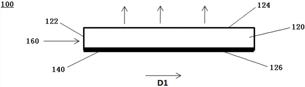
[0035] Please refer to figure 1 , is a structural schematic diagram of a light guide plate with a variable line structure provided by the present invention. The light guide plate 100 in this embodiment can be applied to a backlight module or a lighting fixture. The light guide plate 100 includes a main body 120 and a variable line structure 140. The variable line structure 140 is arranged on the main body 120. Through the variable line structure 140, it can At the same time, the light collecting degree of the light guide plate 100 is changed and the optical trend of light emitted after entering the light guide plate 100 is adjusted.

[0036] In the light guide plate 100, the main body 120 can be a light-transmitting plate or other equivalent light-transmitting parts. The main body 120 mainly includes a light incident surface 122, a first main surface 124, and a second main surface 126. The first main surface 124 and the second main surface The two main surfaces 126 are respec...

Embodiment 2

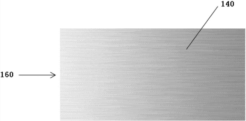
[0045] Such as Figure 6 As shown, it is the second embodiment of the present invention. In this embodiment, the variable lines in the variable line structure 140 form an angle of 45° or 135° with the light incident surface 122, and each independent variable line has a Generate a variable process, the narrower the width of the lines closer to the light incident surface 122, the wider the farther away from the light incident surface 122; there is no variable relationship between adjacent lines parallel to the light incident surface 122, relative to the light incident surface 122 Non-parallel surfaces produce a variable relationship. The closer to the light incident surface 122, the narrower the width of the lines, and the farther away from the light incident surface 122, the wider the width of the lines. The central axes of two adjacent variable lines are parallel to each other.

Embodiment 3

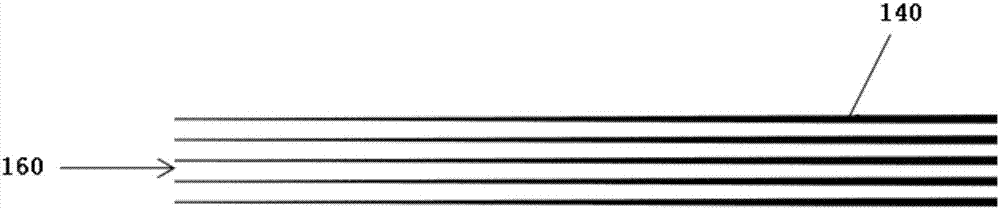
[0047] Such as Figure 7 As shown, it is the third embodiment of the present invention. In this embodiment, the variable lines in the variable line structure 140 form an angle of 0° or 180° with the light incident surface 122, and the variable lines are parallel to the light incident surface 122. On surface 122, there is no variable process on each independent variable line, and its width is fixed, but a variable relationship is formed between adjacent variable lines in turn. The closer to the light incident surface 122, the narrower the width of the line, and the farther away from the light incident surface The wider the line width of 122 is, the central axes of two adjacent variable lines are parallel to each other.

[0048] The manufacturing method of the variable line structure light guide plate provided by the above-mentioned embodiments 1 to 3 includes the following steps:

[0049] S1: According to the requirements of the diaphragm covering in the module design, establi...


PUM


Abstract

The invention provides a variable line structure light guide plate and a manufacturing method of the variable line structure light guide plate. The variable line structure light guide plate comprises an incident light surface (122), a first main surface (124) and a second main surface (126), the second main surface (126) is opposite to the first main surface (124), the incident light surface (122) is connected with the first main surface (124) and the second main surface (126), at least one of the first main surface (124) and the second main surface (126) is provided with a variable line structure (140), and the variable line structure comprises a plurality of variable lines distributed on the first main surface and / or the second main surface of the light guide plate in parallel. The invention further provides an optical module, the optical module comprises a light source, the variable line structure light guide plate, a diffusion plate and a reflection plate, and the variable line structure light guide plate and the optical module are used for the backlight module or an illumination lamp.

Description

technical field [0001] The invention relates to the field of optics, more specifically to a light guide element and an optical component. technical background [0002] Generally, the light guide plate used in the backlight module has a light incident surface, a light output surface and a reflective surface. The light provided by the light source enters the light guide plate from the light incident surface of the light guide plate, and exits from the light exit surface of the light guide plate. Another type of light guide plate used on a lamp has two opposite light exit surfaces, and the light provided by the light source enters the light guide plate and then exits from the two light exit surfaces respectively. In order to make the light passing through the inside of the light guide plate more evenly mixed, laser engraving, V-shaped cross grid engraving, and UV screen printing technology are usually used to engrave or print light guide points on the light guide plate. When ...

Claims


Application Information

Patent Timeline
Patent Type & Authority Applications(China)
IPC IPC(8): G02B6/00
CPCG02B6/0015G02B6/0038G02B6/0043G02B6/0065
Inventor 陶朝新杨政阳波
Owner 深圳市超显科技有限公司
Why Eureka
Try Eureka