Bogie type heating furnace capable of controlling gas flow field

A trolley-type, gas flow technology, applied in the field of metallurgy, can solve the problems of large temperature difference on the surface of the workpiece, over-burning of the workpiece, and increase the difficulty of equipment operation and adjustment, and achieve uniform temperature field, reduce temperature difference in the furnace, and simple structure Effect

Inactive Publication Date: 2017-11-14
上海五钢设备工程有限公司
View PDF5 Cites 1 Cited by
  • Summary
  • Abstract
  • Description
  • Claims
  • Application Information

AI Technical Summary

Problems solved by technology

[0005] At present, the trolley-type heating furnace generally adopts the above-mentioned combustion heating method. When the installation position of the burner in the furnace body is determined, the distribution position of the flow field in the furnace is also determined. It has the following disadvantages: First, it is in the combustion space of the burner There is a local high temperature, and the flame is close to the workpiece, which is easy to overburn the workpiece; second, the temperature in the space in front of the burner is higher than the temperature far away from this position, so that the surface temperature difference of the workpiece is large, even exceeding 60°C
In actual production, encountering workpieces that require high temperature uniformity of steel will greatly increase the difficulty of equipment operation and adjustment

Method used


Image

  • Bogie type heating furnace capable of controlling gas flow field
  • Bogie type heating furnace capable of controlling gas flow field

Examples


Embodiment Construction

[0019] The implementation of the present invention will be illustrated by specific specific examples below, and those skilled in the art can easily understand other advantages and effects of the present invention from the contents disclosed in this specification.

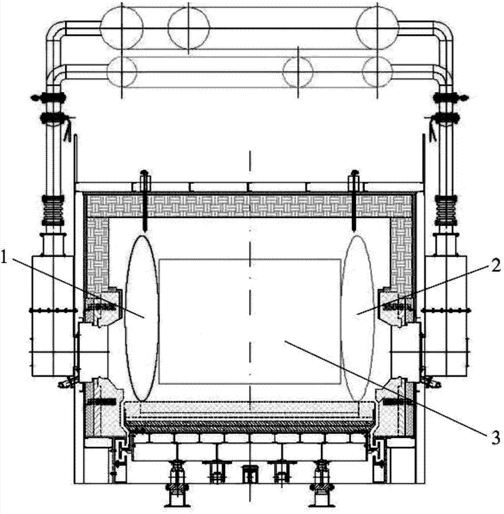
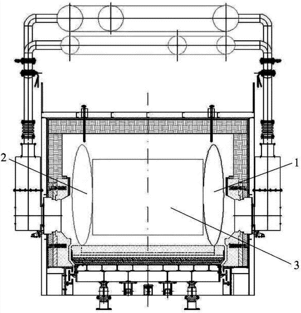
[0020] see Figure 1 to Figure 2 . It should be noted that the structures, proportions, sizes, etc. shown in the drawings attached to this specification are only used to match the content disclosed in the specification, for those who are familiar with this technology to understand and read, and are not used to limit the implementation of the present invention. Limiting conditions, so there is no technical substantive meaning, any modification of structure, change of proportional relationship or adjustment of size, without affecting the effect and purpose of the present invention, should still fall within the scope of the present invention. The disclosed technical content must be within the scope covered. At the sa...


PUM


Abstract

The invention provides a trolley-type heating furnace with controllable gas flow field. A number of burners and smoke outlets are arranged at intervals on the furnace walls on both sides of the furnace. In the high-pressure area, the smoke exhaust port generates a suction force to form a negative pressure area in the area in front of the smoke exhaust port. By controlling the opening and closing of the valve, the opening and closing of the burner is controlled, and the smoke exhaust port is controlled to be exhausted or closed. When the left burner burns, the right side burns. The smoke is exhausted from the smoke exhaust port, and the smoke is exhausted from the left smoke exhaust port when the right burner is burning, and the relative positions of the high pressure area and the negative pressure area in the furnace are exchanged regularly. The invention has the advantages of simple structure, convenient use and easy realization, and realizes the control of fluid flow in the furnace by controlling the furnace pressure in different regions. Regularly change the gas flow direction in the furnace, reduce the temperature difference in the furnace, make the temperature field tend to be uniform, and make the temperature uniformity of the high-temperature heating furnace within ±10°C. The influence of the local high temperature of the flame on the temperature field of the effective heating area is avoided, thereby avoiding the risk of the workpiece being burned.

Description

technical field [0001] The present invention relates to the field of metallurgy; [0002] In particular, it relates to a trolley-type heating furnace with a controllable gas flow field. Background technique [0003] The trolley-type heating furnace is used to produce mold steel, bearing steel, high alloy steel and other products. The trolley-type heating furnace is a batch-type variable temperature furnace, the furnace is not partitioned, and the furnace temperature changes with time according to the prescribed heating program. The trolley-type heating furnace has a chamber-type furnace, and the bottom of the furnace is a movable trolley. The workpiece is arranged on the special pad iron evenly distributed on the surface of the trolley. When heating, the trolley is pulled into the furnace by the traction mechanism; after heating , the trolley is pulled out of the furnace to unload by the traction mechanism. [0004] In the prior art, some trolley-type heating furnaces ado...

Claims


Application Information

Patent Timeline
Patent Type & Authority Applications(China)
IPC IPC(8): F27B9/14F27B9/36
CPCF27B9/14F27B9/36
Inventor 杨宏飞
Owner 上海五钢设备工程有限公司
Why Eureka
Try Eureka