Soaking sintering process based on combustible gas blowing

A thermal sintering and process technology, applied in the field of sintering, to achieve the effects of improving quality, reducing emissions, and prolonging high temperature holding time

Inactive Publication Date: 2017-11-17
ZHONGYE-CHANGTIAN INT ENG CO LTD
View PDF3 Cites 21 Cited by
  • Summary
  • Abstract
  • Description
  • Claims
  • Application Information

AI Technical Summary

Problems solved by technology

[0018] The purpose of the present invention is to provide a homogeneous sintering gas addition method to solve the problem of how to reduce solid fuel consumption on the premise of improving sinter quality and reduce the emission of carbon dioxide from blast furnaces

Method used


Image

  • Soaking sintering process based on combustible gas blowing
  • Soaking sintering process based on combustible gas blowing
  • Soaking sintering process based on combustible gas blowing

Examples


Embodiment approach

[0135] According to the second embodiment provided by the present invention, a soaking sintering device based on combustible gas injection is provided:

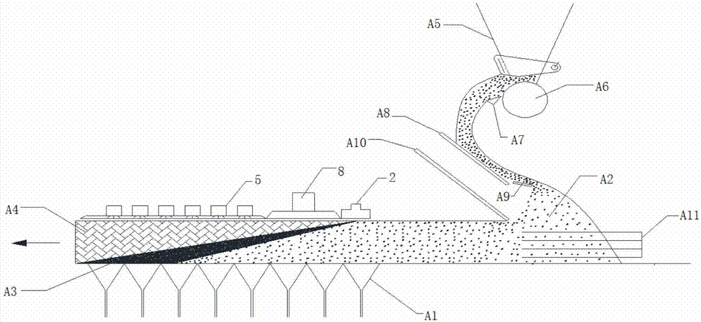
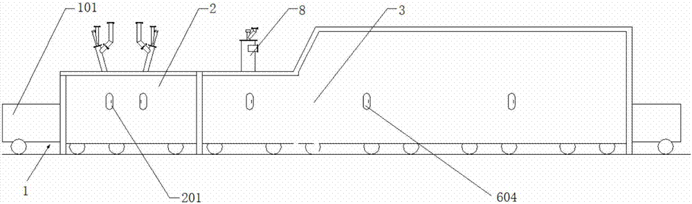
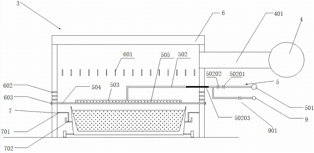
[0136] A soaking sintering device based on combustible gas injection, comprising a sintering machine 1 , an ignition furnace 2 and an auxiliary combustion device 3 . The sintering machine 1 includes a trolley 101 , and along the running direction of the trolley 101 , the ignition furnace 2 and the auxiliary combustion device 3 are sequentially arranged above the trolley 101 . The auxiliary combustion device 3 includes a hot air device 4 , an injection device 5 and an auxiliary combustion cover 6 . The hot air device 4 and the blowing device 5 are provided on the auxiliary combustion cover 6 . The hot air device 4 includes a hot air duct 401 . The hot air duct 401 extends into or leads into the auxiliary combustion hood 6 . The injection device 5 includes a gas main pipe 501 , a gas branch pipe 502 , an injection pipe 503 a...

Embodiment 1

[0166]A multi-stage enhanced auxiliary sintering type ignition holding furnace device comprises a sintering machine 1 , an ignition device 2 and an auxiliary combustion device 3 . The sintering machine 1 includes a trolley 101 , and along the running direction of the trolley 101 , the ignition device 2 and the auxiliary combustion device 3 are sequentially arranged above the trolley 101 . The auxiliary combustion device 3 includes a hot air device 4 , an injection device 5 and an auxiliary combustion cover 6 . The hot air device 4 and the blowing device 5 are provided on the auxiliary combustion cover 6 . The hot air device 4 includes a hot air duct 401 . The hot air duct 401 extends into or leads into the auxiliary combustion hood 6 . The injection device 5 includes a gas main pipe 501 , a gas branch pipe 502 , an injection pipe 503 and a bracket 504 . The gas header 501 is provided outside the auxiliary combustion hood 6 . One end of the gas branch pipe 502 is connected ...

Embodiment 2

[0168] Example 1 is repeated, except that the inner space of the auxiliary combustion hood 6 is further provided with a fairing device 601 . The straightening device 601 is located above the blowing pipe 503 of the blowing device 5 but below the air outlet of the hot air duct 401 of the hot air device 4 . The rectifying device 601 is a rectifying plate.


PUM

PropertyMeasurementUnit
porosityaaaaaaaaaa

Abstract

The invention discloses a soaking sintering process based on combustible gas blowing. The soaking sintering process comprises the following steps: (1) batching; (2) charging; (3) igniting; (4) sintering; (5) performing heat preservation and heat supplementation: when agglomerate is formed on the surface layer of a sintering mix materiel after ignition, blowing a sintering flue gas or ring cooling machine hot gas to the surface of the sintering mix materiel by arranging a heat preservation and heat supplementation device on the sintering mix materiel; (6) performing soaking sintering based on combustible gas blowing: blowing a combustible gas to the part above the surface layer of the sintering mix materiel to enable the combustible gas to be combusted in the combustion layer of the sintering bed; and (7) completing sintering, and discharging. The invention provides a gas feeding method and device for uniform sintering, and aims to solve the problems of reducing the solid fuel consumption on the premise of improving the sintered ore quality and further reducing the carbon dioxide emission of the blast furnace.

Description

technical field [0001] The invention relates to a soaking sintering process based on combustible gas injection, in particular to a soaking sintering device based on combustible gas injection and a method for using the same, belonging to the field of sintering. Background technique [0002] With the development of modern industry, the steel industry has become increasingly saturated, with excess production capacity. At present, most steel companies are losing money. In this case, it is urgent to reduce costs, save energy and reduce emissions, especially how to improve the existing sintering technology to achieve this goal. [0003] The sintering process is a key link in the ironmaking process. The principle is to mix various powdered iron-containing raw materials with appropriate amount of fuel and flux, add an appropriate amount of water, and then mix and pelletize the materials on the sintering equipment. A series of physical and chemical changes, sintered into a block, an...

Claims


Application Information

Patent Timeline
Patent Type & Authority Applications(China)
IPC IPC(8): C22B1/22
CPCC22B1/22
Inventor 周志安周浩宇丁智清李康夏春才陈鹏胡兵景涛刘水石
Owner ZHONGYE-CHANGTIAN INT ENG CO LTD
Why Eureka
Try Eureka