Laser backlight device for display system

A technology for a backlight device and a display system, applied in the field of lasers, can solve the problems of occupying positive space, limited divergence, and inability to meet the thickness of the display screen, achieving a large divergence angle, high reflection efficiency, and meeting the requirements of the backlight source. Effect

Pending Publication Date: 2017-11-17
深圳市阿集比光电科技有限公司
View PDF0 Cites 1 Cited by
  • Summary
  • Abstract
  • Description
  • Claims
  • Application Information

AI Technical Summary

Problems solved by technology

[0003] The disadvantage of the existing technology is that the laser light source used for display is usually a front-projection method, and the laser light source needs to be kept at a certain distance from the front-projection screen. Therefore, the whole device needs to occupy a certain front space, which cannot meet the thin thickness of the display screen. Requirements, in addition the laser backlight source in the prior art adopts cylindrical mirror and a word wave mirror as the light divergence element, but the lateral maximum divergence angle of the cylindrical mirror and the word wave mirror can only be 120 degrees, the degree of divergence has certain limitations

Method used


Image

  • Laser backlight device for display system
  • Laser backlight device for display system
  • Laser backlight device for display system

Examples


Embodiment Construction

[0028] In order to enable those skilled in the art to better understand the technical solutions of the present invention, the present invention will be further described in detail below in conjunction with the accompanying drawings.

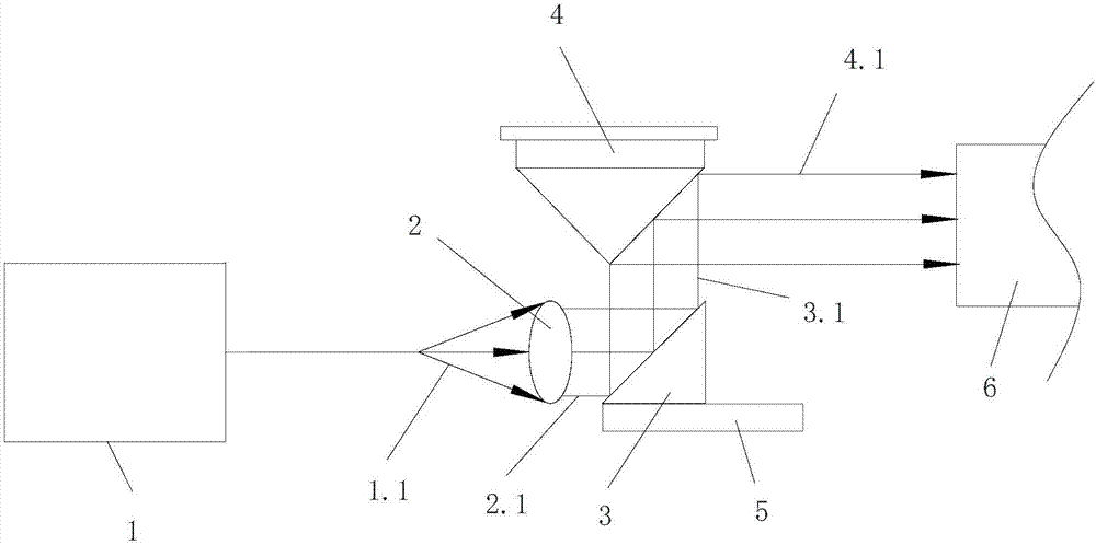
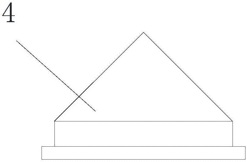
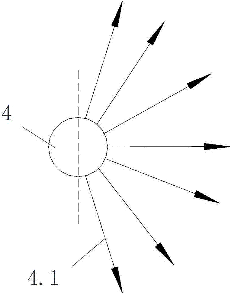
[0029] like Figure 1-6 As shown, a laser backlight device for a display system provided by an embodiment of the present invention includes at least one set of backlight generating assemblies, each set of backlight generating assemblies includes an incident laser mechanism 1, and each set of backlight generating assemblies also includes a lens 2, a plane Reflecting mirror 3 and conical mirror 4, lens 2 is used for collimating and shaping the incident laser beam 1.1 of incident laser mechanism 1 into the first quasi-parallel laser beam 2.1; 2.1 Reflecting and turning into a second quasi-parallel laser beam 3.1; the conical mirror 4 is used to diverge the second quasi-parallel beam into a backlight 4.1.

[0030] Specifically, the incident laser me...


PUM

PropertyMeasurementUnit
Cone angleaaaaaaaaaa

Abstract

The invention discloses a laser backlight device for a display system. The laser backlight device comprises at least one set of backlight generating assembly, wherein each set of backlight generating assembly comprises an incident laser mechanism, and each set of backlight generating assembly further comprises a lens, a planar reflecting mirror plane and a conical mirror plane, wherein the lens is used for collimating and shaping an incident laser beam of the incident laser mechanism into a first quasi-parallel laser beam; the planar reflecting mirror plane is used for reflecting the first quasi-parallel laser beam and turning the first quasi-parallel laser beam into a second quasi-parallel; and the conical mirror plane is used for diverging the second quasi-parallel light beam into a backlight. The laser backlight device for the display system only comprises the lens, the planar reflecting mirror plane and the conical mirror plane, the occupied space is small, so that the thickness of a display screen can be reduced; and meanwhile, the conical mirror plane can be used for enabling the incident light beam to be diverged by 180 degrees, the reflection efficiency is high, the divergence angle is large, and the requirement of the backlight source of a large-size display screen can be met.

Description

technical field [0001] The invention relates to laser technology, in particular to a laser backlight device for a display system. Background technique [0002] At present, in the field of display, backlight sources include organic light-emitting diodes (OLEDs), quantum dots (QLEDs) and lasers. Among them, lasers as light sources have the characteristics of monochromaticity, coherence, high brightness, and long life. It can be as high as more than 90% of the color gamut of the human eye, which is a level higher than the highest 62% color gamut coverage of LED displays. The higher color gamut coverage makes the display screen look more real, transparent and layered. [0003] The disadvantage of the existing technology is that the laser light source used for display is usually a front-projection method, and the laser light source needs to be kept at a certain distance from the front-projection screen. Therefore, the whole device needs to occupy a certain front space, which can...

Claims


Application Information

Patent Timeline
IPC IPC(8): F21S8/00F21V13/06F21Y113/10F21Y115/30
CPCF21S8/00F21V13/06F21Y2115/30F21Y2113/10
Inventor 房旭光杨理君黄辉易林泽
Owner 深圳市阿集比光电科技有限公司
Why Eureka
Try Eureka