Wind-induced gyromagnetic excitation type piezoelectric generator

A magnetic excitation and generator technology, which is applied to wind power generation, wind power generators, and wind power generators in the same direction as the wind. It can solve the problems of large changes in the bending deformation of piezoelectric vibrators, damage to piezoelectric sheets, and poor power generation effects, etc. problem, to achieve the effect of strong power generation and power supply capacity, high reliability, and effective frequency bandwidth

Pending Publication Date: 2017-11-17
ZHEJIANG NORMAL UNIVERSITY
View PDF9 Cites 5 Cited by
  • Summary
  • Abstract
  • Description
  • Claims
  • Application Information

AI Technical Summary

Problems solved by technology

The common feature of the above-mentioned piezoelectric generators is that they all use the bidirectional bending deformation of the piezoelectric vibrator to generate electricity. The biggest disadvantage is that the bending deformation of the piezoelectric vibrator varies greatly at different wind speeds, and the piezoelectric sheet is prone to excessive tensile stress due to large deformation. Large and damaged, but the power generation effect is not good when the deformation is small

Method used


Image

  • Wind-induced gyromagnetic excitation type piezoelectric generator
  • Wind-induced gyromagnetic excitation type piezoelectric generator
  • Wind-induced gyromagnetic excitation type piezoelectric generator

Examples


Embodiment Construction

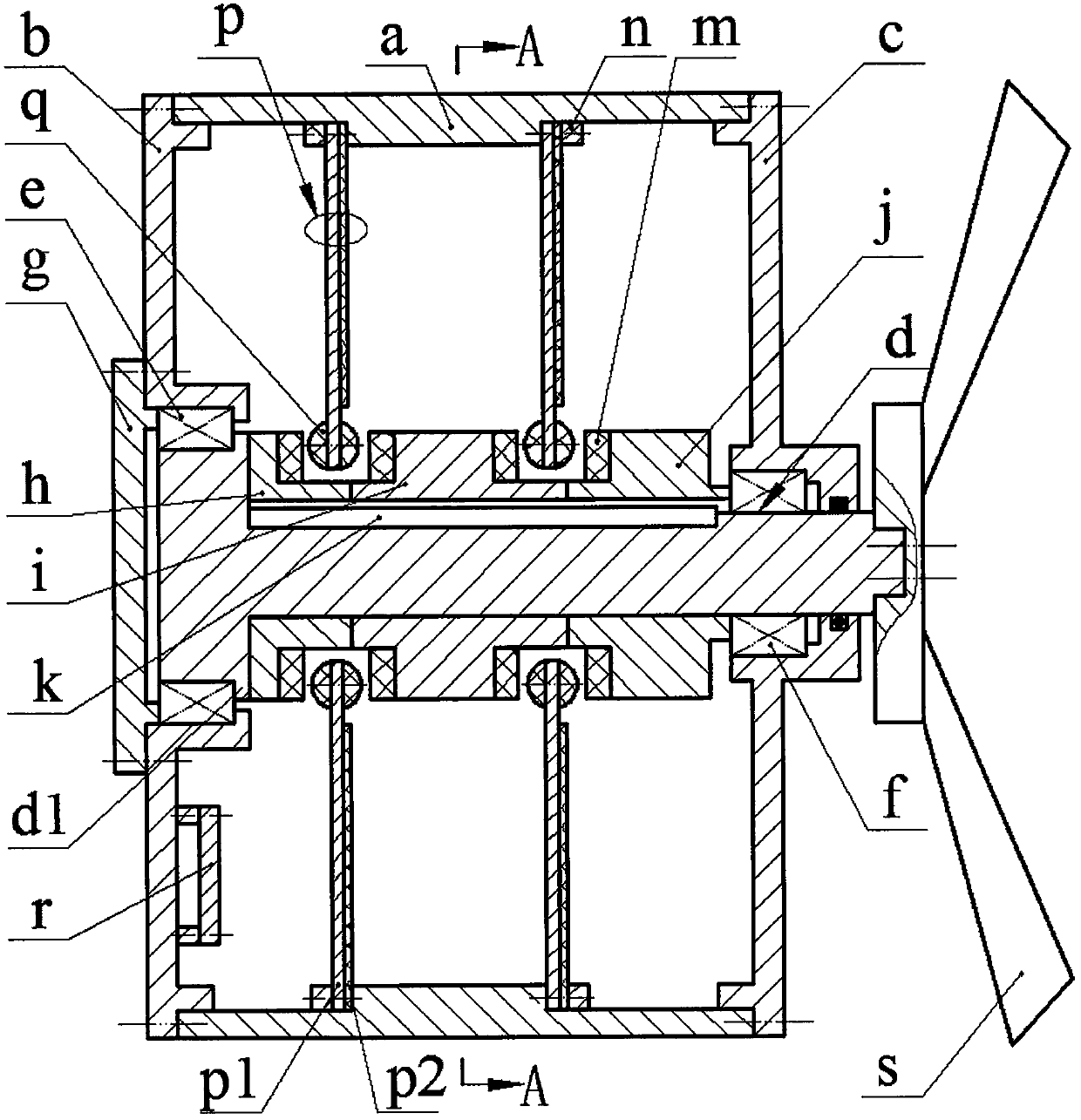
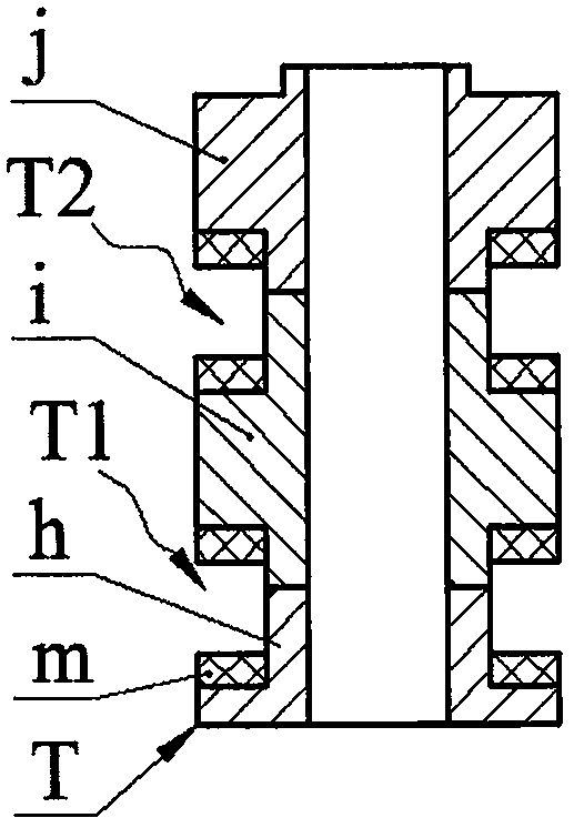
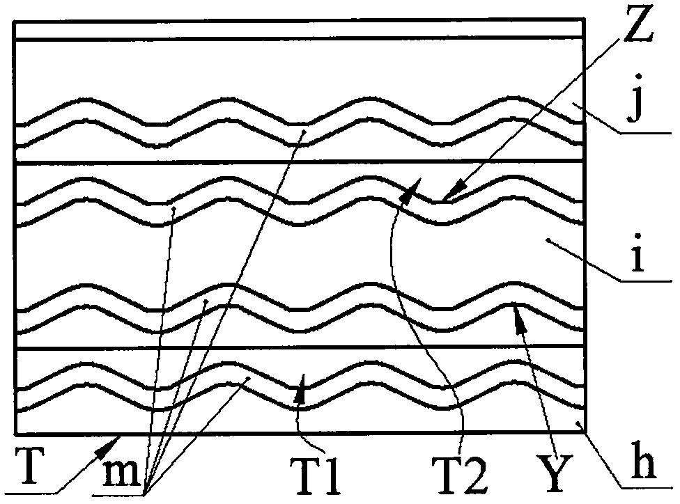
[0012] The left and right ends of the shell a are respectively installed with a left end cover b and a right end cover c through screws; the left end of the main shaft d is installed on the left end cover b through the left bearing e, and the right end of the main shaft d is installed on the right end cover c through the right bearing f; The bearing cover g is installed on the left end cover b through screws, and the outer ring of the left bearing e is pressed against the left end cover b, the shoulder d1 of the main shaft d is pressed against the inner ring of the left bearing e, and the main shaft d is from left to right. There are left sleeve h, intermediate sleeve i and right sleeve j in turn, the right sleeve j leans against the inner ring of the right bearing f, the outer ring of the right bearing f leans against the right end cover c, and the main shaft d The blade s is installed at the right end of the blade s; the left bushing h, the middle bushing i, the right bushing...


PUM


Abstract

The invention relates to a wind-induced gyromagnetic excitation type piezoelectric generator and belongs to the technical field of new energy. The left and right ends of a shell are respectively provided with a left end cover and a right end cover. A main shaft is mounted on the left and right end covers through a bearing. A left shaft sleeve, a middle shaft sleeve and a right shaft sleeve are sequentially sleeved on the main shaft from left to right. A blade is arranged on the right end portion of main shaft. Magnetic cam rings are arranged on the right side of the left shaft sleeve, the two sides of the middle shaft sleeve and the left side of the right shaft sleeve, respectively. The left shaft sleeve, the middle shaft sleeve, the right shaft sleeve and the magnetic cam rings arranged on the shaft sleeves together form a cam, a left cam slot and a right cam slot. Piezoelectric vibrators are arranged on bosses on the inner wall of the shell. The free ends of the piezoelectric vibrators are provided with magnetic blocks. The magnetic blocks are arranged in left and right cam slots. The reaction force between magnetic blocks and adjacent magnetic cam rings is a repulsive force. When the magnetic blocks are in contact with the vertexes of cam surfaces on the right sides of the left and right cam slots, the bending deformation of the piezoelectric vibrators does not occur. When the magnetic blocks are in contact with the vertexes of cam surfaces on the left sides of the left and right cam slots, the deformation amount of two lamination composite layers at the free ends of the piezoelectric vibrators is smaller than the allowable value thereof.

Description

technical field [0001] The invention belongs to the technical field of new energy, and in particular relates to a wind-induced gyromagnetic excitation piezoelectric generator, which provides real-time energy supply for micro-power systems such as wireless sensor nodes. Background technique [0002] Wind energy widely exists in nature, and wind power generation has become one of the mainstream energy sources in the world today. In the past, people only paid attention to the research of large-scale wind power generation system. Its research on micro-wind generators that provide continuous energy supply has attracted extensive attention from scholars at home and abroad. The micro-wind generators that have been proposed so far are basically based on the electromagnetic principle and the piezoelectric principle. Because the piezoelectric generator will not generate electromagnetic interference during the power generation process, it is more suitable for the application requireme...

Claims


Application Information

Patent Timeline
IPC IPC(8): H02N2/18F03D1/00F03D9/25
CPCH02N2/185F03D1/00F03D9/25Y02E10/72
Inventor 王淑云黄乐帅陈松
Owner ZHEJIANG NORMAL UNIVERSITY
Why Eureka
Try Eureka