Method and device for transmission of light pilot tone signals
A transmission method and signal technology, which is applied in the field of optical communication, can solve the problems such as the inability to dynamically adjust the adjustment coefficient of the optical modulation signal of the PON system, and achieve the effect of ensuring reliability and improving sensitivity
- Summary
- Abstract
- Description
- Claims
- Application Information
AI Technical Summary
Problems solved by technology
Method used
Image

Examples
Embodiment 1
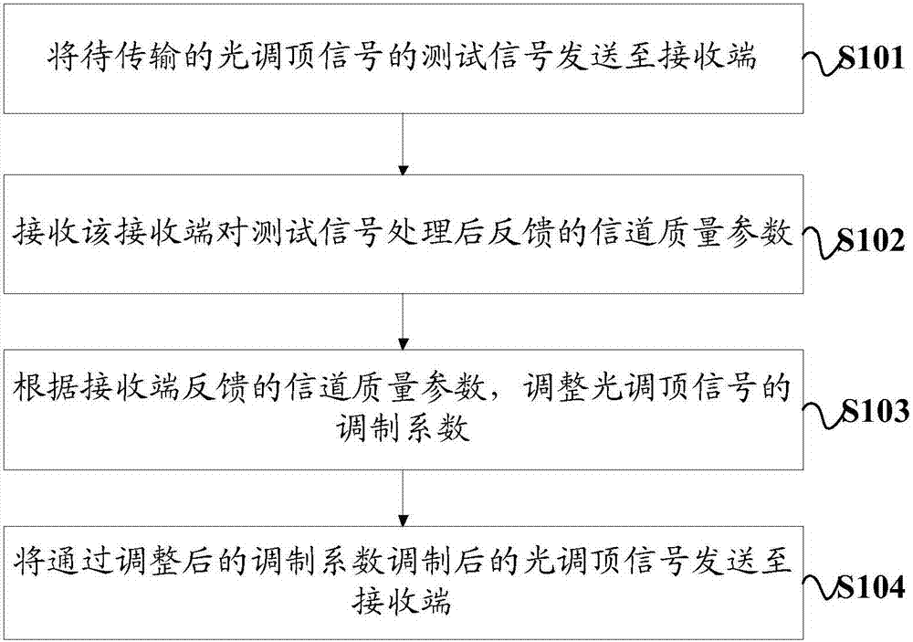
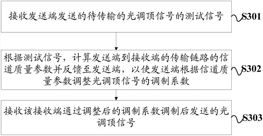
[0043] Such as figure 1 As shown, the embodiment of the present invention provides a method for transmitting an optical top signal, which is applied to the sending end, and specifically includes the following steps:
[0044] Step S101: Send the test signal of the optical top adjustment signal to be transmitted to the receiving end.
[0045] Among them, the optical modulation signal is based on digital modulation technology, which is a mixed signal formed after different types of signals are modulated to a suitable carrier through waveform conversion. The test signal can be modulated with the service signal in the optical top signal, and sent from the sending end to the receiving end. It is worth pointing out that the test signal may be an uplink test signal or a downlink test signal. Take the OLT equipment (Optical Line Terminal, Optical Line Terminal) and ONU equipment (Optical Network Unit, Optical Network Unit) in the PON system as an example, wherein, the transmission link...
Embodiment 2
[0053] Based on the first embodiment above, this embodiment will further describe the transmission method of the optical ceiling adjustment signal in combination with specific application scenarios.
[0054] Wherein, the above-mentioned test signal can be a pseudo-random sequence, and step S101 specifically includes:
[0055] The pseudo-random sequence is modulated according to the current reference modulation coefficient of the optical modulation signal to be transmitted; and the modulated pseudo-random sequence is sent to the receiving end.
[0056] Wherein, the pseudo-random sequence can be sent together with the service signal, that is, the pseudo-random sequence is modulated by the modulated carrier, modulated with the service signal according to the current reference modulation coefficient, and sent from the transmitting end to the receiving end. Wherein, the carrier frequency of the modulated carrier is greater than N times the transmission rate of the pseudo-random seq...
Embodiment 3
[0066] Based on the first embodiment above, this embodiment will further describe the transmission method of the optical ceiling adjustment signal in conjunction with another specific application scenario.
[0067] Wherein, the above-mentioned test signal may be an auxiliary management and control channel AMCC signal, and the current reference modulation coefficient of the optical modulation signal to be transmitted. Step S101 specifically includes:
[0068] Modulate the AMCC signal according to the reference modulation coefficient; send the modulated AMCC signal and the reference modulation coefficient to the receiving end.
[0069] Wherein, the AMCC signal and the current reference modulation factor are sent together with the service signal, that is, after the AMCC is modulated by the modulated carrier, it is modulated with the service signal according to the current reference modulation factor, and sent from the transmitting end to the receiving end. Wherein, the carrier fr...
PUM
 Abstract
Description
Claims
Application Information
 - Generate Ideas
- Intellectual Property
- Life Sciences
- Materials
- Tech Scout
- Unparalleled Data Quality
- Higher Quality Content
- 60% Fewer Hallucinations
Browse by: Latest US Patents, China's latest patents, Technical Efficacy Thesaurus, Application Domain, Technology Topic, Popular Technical Reports.
© 2025 PatSnap. All rights reserved.Legal|Privacy policy|Modern Slavery Act Transparency Statement|Sitemap|About US| Contact US: help@patsnap.com