An ejection device that enables steady and sustained acceleration of objects

An ejection device and a stable technology, which is applied in the direction of launch/drag transmission, etc., can solve the problems that the aircraft cannot reach the take-off speed, burn out the coil electronic devices, and the acceleration becomes low in the later stage, so as to achieve uniform ejection speed and low maintenance cost , The effect of long boost distance

Active Publication Date: 2019-06-18
SICHUAN CHUANGWEI NETWORK TECH CO LTD
View PDF5 Cites 0 Cited by
  • Summary
  • Abstract
  • Description
  • Claims
  • Application Information

AI Technical Summary

Problems solved by technology

The electromagnetic ejection structure currently being researched and tried in a few countries is very technical, it is difficult to master in a short time, and it must have a high capacitance. If it is used continuously, the electromagnetic device will generate high temperature, which will burn out the coil and other electronic devices. Therefore, Inconvenient to use in our country
[0003] For decades, many countries have conducted serious research on the spring ejection structure. Although the initial acceleration of the spring is high, its later acceleration becomes lower, making the aircraft unable to reach the take-off speed. Even if the spring is increased or the spring is increased Elastic force can't change this defect, so it can't boost the aircraft well

Method used


Image

  • An ejection device that enables steady and sustained acceleration of objects
  • An ejection device that enables steady and sustained acceleration of objects
  • An ejection device that enables steady and sustained acceleration of objects

Examples


Embodiment Construction

[0029] The present invention will be further described below with reference to the accompanying drawings and embodiments, and the mode of the present invention includes but not limited to the following embodiments.

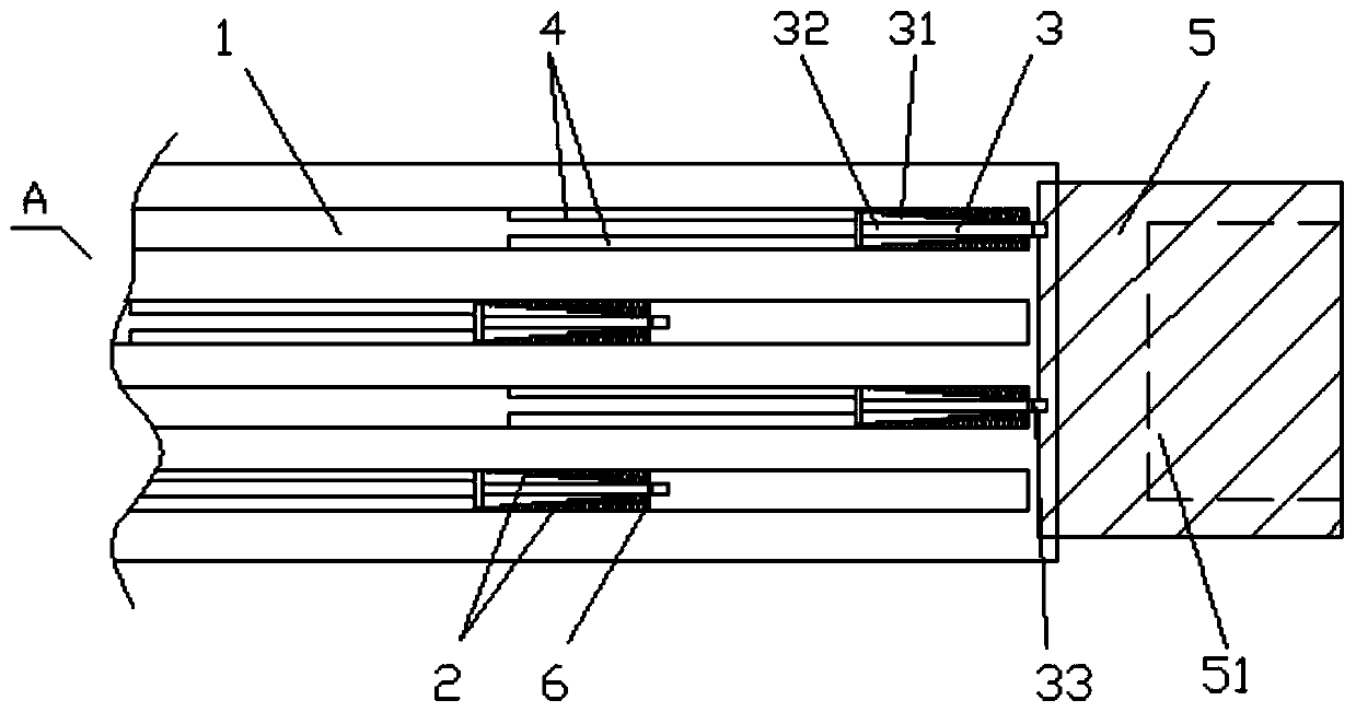
[0030] The purpose of this embodiment is to provide an ejection structure capable of stably accelerating an object, such as figure 1 As shown, the ejection structure in this embodiment is mainly used for the purpose of multi-stage ejection and continuous boosting of the aircraft. Specifically, the ejection structure includes a plurality of ejection paths 1 parallel to each other. There is an ejection structure, and the ejection structures in the adjacent ejection paths are misplaced; the installation positions of the ejection structures in the two ejection paths of the alternate ejection path 1 are the same and are triggered synchronously, so as to achieve the purpose of uniform ejection speed, so that the aircraft is evenly stressed and accelerates smoothly , to ...


PUM


Abstract

The invention discloses an ejection device capable of stabilizing an object and accelerating continuously. The ejection device comprises a plurality of ejection channels parallel one another, a plurality of ejection structures are arranged in the each of the ejection channels, the ejection structures in adjacent ejection channels are arranged in a staggered manner, and the ejection structures in alternate ejection channels are arranged in an aligned manner and are triggered synchronously; each of the ejection structures comprises a spring plate, a compression spring, an ejection auxiliary plate, baffle blocks and an ejection plate; the spring plate is vertically arranged in the ejection channel, and one end of the compression spring is fixed on the spring plate; the two baffle blocks are separately arranged on two sides above the ejection channel in front of the moving end of the compression spring; the ejection auxiliary plate comprises a locking bottom plate, a ridge and a locking block; and a locking groove matched with the locking block is formed in the bottom of the ejection plate. The ejection structures can accelerate the object effectively, the boosting distance of the ejection structures is long, the ejection speed is uniform, the object is steadily accelerated, and the safety in use of the object and related equipment can be fully guaranteed.

Description

technical field [0001] The invention relates to a booster device, in particular to an ejection structure capable of stably accelerating an object (especially an aircraft). Background technique [0002] At present, most countries with aircraft carriers in the world generally use steam-type ejection structures. The manufacture of such steam-type ejection structures is relatively complicated, and steam boilers, pressure storage tanks, large pistons and cylinders, and seawater desalination equipment must be installed. Using the steam ejection structure, it is necessary to maintain enough high-pressure steam at ordinary times, otherwise, in an emergency, the carrier-based aircraft will not only be unable to take off on time, but will also delay the aircraft. Vapor compression devices such as cylinders and pistons in the steam ejection structure must maintain high sealing performance for a long time, otherwise the ejection structure will be insufficiently powered, and the safety o...

Claims


Application Information

Patent Timeline
Patent Type & Authority Patents(China)
IPC IPC(8): B64F1/06
CPCB64F1/06
Inventor 高梓洋
Owner SICHUAN CHUANGWEI NETWORK TECH CO LTD
Why Eureka
Try Eureka